CNC Computer Numerical Control machines are widely used in manufacturing industry. Traditional machines such as vertical millers, centre lathes, shaping machines, routers etc.... operated by a trained engineer have, in many cases, been replaced by computer control machines.
ADVANTAGES
1.
CNC machines can be used continuously 24 hours a day, 365 days a year and only
need to be switched off for occasional maintenance.
2. CNC machines are programmed with a design
which can then be manufactured hundreds or even thousands of times. Each
manufactured product will be exactly the same.
3. Less skilled/trained people can operate
CNCs unlike manual lathes / milling machines etc.. which need skilled engineers.
4. CNC machines can be updated by improving
the software used to drive the machines
5. Training in the use of CNCs is available
through the use of ‘virtual software’. This is software that allows the operator
to practice using the CNC machine on the screen of a computer. The software is
similar to a computer game.
6. CNC machines can be programmed by
advanced design software such as Pro/DESKTOP®, enabling the
manufacture of products that cannot be made by manual machines, even those used
by skilled designers / engineers.
7. Modern design software allows the
designer to simulate the manufacture of his/her idea. There is no need to make a
prototype or a model. This saves time and money.
8. One person can supervise many CNC
machines as once they are programmed they can usually be left to work by
themselves. Sometimes only the cutting tools need replacing occasionally.
9. A skilled engineer can make the same component many times. However, if each component is carefully studied, each one will vary slightly. A CNC machine will manufacture each component as an exact match.
DISADVANTAGES
1. CNC machines are more expensive than
manually operated machines, although costs are slowly coming down.
2. The CNC machine operator only needs basic
training and skills, enough to supervise several machines. In years gone by,
engineers needed years of training to operate centre lathes, milling machines
and other manually operated machines. This means many of the old skills are been
lost.
3. Less workers are required to operate CNC
machines compared to manually operated machines. Investment in CNC machines can
lead to unemployment.
4. Many countries no longer teach pupils /
students how to use manually operated lathes / milling machines etc... Pupils /
students no longer develop the detailed skills required by engineers of the
past. These include mathematical and engineering skills.
In Industry it is not efficient or profitable to make everyday products by hand. On a CNC machine it is possible to make hundreds or even thousands of the same item in a day. First a design is drawn using design software, then it is processed by the computer and manufactured using the CNC machine. In industry, CNC machines can be extremely large.
CNC stands for Computer Numerical Control. This means a computer converts the design produced by Computer Aided Design software (CAD), into numbers. The numbers can be considered to be the coordinates of a graph and they control the movement of the cutter. In this way the computer controls the cutting and shaping of the material.
The X, Y and Z axis control the movement of the cutter on a 3D CNC machine. This allows materials to be machined in three directions (3D manufacture).
The design (produced on CAD, Computer Aided Design software) has been converted into coordinates. The cutter is instructed to go from one coordinate to another. A simple plastic block such as this may have a thousand coordinates.
A production flow chart is very important when
planning the manufacture of a product. Although CNC products can be small,
quality in manufacture is crucial. Draw a flowchart similar to the one below.
This should explain every stage of the manufacture of a product you have
produced through the use of a CNC machine. Include a number of quality checks.
Quality control is an essential part of any project and at any stage the product
may be rejected if a fault or inaccuracy is found.
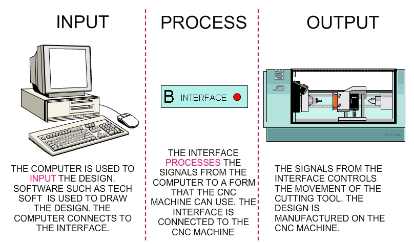
A CNC production facility needs three pieces of equipment:
A Computer.
The computer is used to draw the design. CAD - Computer Aided Design software is
used for this purpose. However, the design is only a picture and the CNC machine
cannot use this to manufacture the product. The computer software must also
convert the drawing into numbers (coordinates) that the CNC machine can use when
it starts to cut and shape the material.
An Interface.
A computer cannot be directly connected to a CNC machine. The computer is
connected to an interface. Modern CNC machines have a ‘built in’ or integral
interface, which appears part of the CNC machine. This circuit converts the
signals from the computer to a form that the CNC machine understands. Older CNC
machines have a separate ‘box’ called the interface. The signals are in the form
of digital signals when they are sent to the CNC machine.
CNC (Computer Numerical Control) Machine.
The signals from the interface control the motors on the CNC machine. The
signals determine the way the vice moves. The vice moves in three directions X,
Y and Z. (Horizontally, vertically and depth). The signals also control the
speed of the cutting tool.
The whole process of designing and making an item on the CNC machine can be split into three aspects INPUT-PROCESS-OUTPUT. The diagram below explains this system.
There are two types of computer aided design software. 2D design software allows the designer to design shapes with very limited three dimensional properties. Do not underestimate the designs that can be achieved through 2D software
1. The design is drawn using software such as TechSoft 2D Design. At first
appearance this software looks basic but, depending on the skill of the
designer, quite complex designs can be produced.
The example shown is a simple block of material with initials.
2. When the design is complete the drawing is processed. This converts the
drawing into a detailed series of X, Y and Z coordinates. Processing must take
place before the CNC machine can cut the design from material.
When the CNC machine shapes the material the cutter follows the coordinates, in
sequence, until the shape has been manufactured.
3. Most CAD/CAM software allows the designer to test the manufacture of his/her design on a computer rather than actually making it. This saves time and materials. Testing designs is carried out using ‘simulation’ software (Boxford use ‘CAD/CAM Design Tools’ software). When the design is run through simulation software the computer displays the manufacturing on the screen. It also checks whether or not the design can be manufactured successfully. Many designs have to be altered before they can be made by a CNC machine.
After all the testing and improvements to the design, it can finally be manufactured on a CNC machine.
3D Design software such as Pro/DESKTOP® allows the designer to produce three dimensional representations of his/her ideas. When completed the design can be viewed on the screen and it can even be revolved and examined at any angle. 3D software such as Pro/DESKTOP® is much more complex than 2D software such as TechSoft 2D design. It requires specialist training before it can be used competently.
1. The designer draws up the design using
software such as Pro/DESKTOP®. The design can be examined in detailed
and if modifications/alterations are needed they can be made on the screen.
Software of this type allows the designer to model his/her idea on the screen
rather than make/manufacture an expensive model. Good 3D software allows the
designer to design almost any item.
2. The design is processed. When the design has been completed using Pro/DESKTOP® it must be exported as a stereo lithography file. This type of file can be imported into processing software such as Boxford’s 3D-GeoCAM which converts the drawing into a long list of coordinates. Each set of coordinates is called a GM code.
3. Most CAD/CAM software allows the designer to test the manufacture of his/her design on a computer rather than actually making it. This saves time and materials. Testing designs is carried out using ‘simulation’ software. When the design is run through simulation software the computer displays the manufacturing on the screen. It also checks whether or not the design can be manufactured successfully. Many designs have to be altered before they can be made by a CNC machine.
4. An advanced CNC machine such as the A3 HSRi² (Boxford Machine Tools, Halifax, England) can be used to manufacture the three dimensional product. This CNC is both fast and accurate making suitable for school and industrial use.
A CNC machine is normally controlled by a computer and software. However, most CNC machines have a range of controls for manual use. It is rare for a CNC machine to be used manually as simple operations are best carried out on cheap/basic/manual machines. When a CNC machine is used manually it is been used well below its capability and specification.
RESET BUTTON: The must important control button is usually the reset button. When the CNC machine is turned on, the reset button is pressed by the machine operator. This ‘zeros’ the cutter, moving the cutter to coordinates 0,0,0 on the X,Yand Z axis. In simple terms, the reset button moves the cutter to the corner of the machine, above the work table. If the reset button is not pressed, it is possible that the CNC machine will start cutting the material in the wrong place or even miss cutting the material and plunge into the work table.
MANUAL CONTROL: The cutter can be controlled
manually although this is rarely needed. The ‘X’ and ‘Y’ buttons control the
movement of the cutter along the horizontal surfaces. The ‘Z’ buttons control
depth and up / down movement.
STOP BUTTON: Most control panels have stop buttons.
When pressed these stop the machine very quickly.
SPEED AND FEED: On some CNC machines it is possible
to manually vary the speed and feed of the cutter.
One of the few operations that the machine operator carries out is to change
the cutting tool. Each CNC machine has a range of cutting tools. Straight
cutters, chamfer V-groove and radius cutters are some examples. If a detailed
design is being manufactured, it may be necessary to change the cutting tool at
least once during the manufacturing process. It is very important that all the
cutters are set up to exactly to the same length in the collet. If this is not
done the material being machined will be machined at incorrect depths.
A special depth gauge is used to accurately set up the cutting tools. (see
diagram below). This ‘rule’ applies to all CNC machines although different
techniques may be used depending on the type of the CNC machine.
CNC machines are very safe to use as they are designed to be as safe as possible. One of the main advantages of CNC machines is that they are much safer than manually operated machines. The animation below shows a Boxford A3 HSRi² CNC Router with many of its safety features labelled.
1. Most modern CNC machines are designed
so that the cutting tool will not start unless the guard is in position. Also,
the best CNC machines automatically lock the guard in position whilst the cutter
is shaping material. The guard can only be opened if the cutter has stopped.
2. It is essential that pupils / students /
machine operators receive ‘quality’ instruction before attempting to use any CNC
equipment.
3. CNC routers, used for shaping materials
such as woods and plastics, have built in extraction. Dust can be very dangerous
if inhaled and can also cause eye irritation. The CNC Router shown above has an
outlet for an extraction unit. As the router is fully enclosed, dust cannot
escape into the atmosphere. If an extraction unit is attached the dust is
removed automatically. Most manually operated machine routers have very limited
extraction systems which leave some dust in the air.
4. The CNC router above has a single phase
electrical supply. Most older machines such as manually operated milling
machines and centre lathes have three phase supplies. A single phase electrical
supply can be ‘plugged’ into any available socket. The electrical supply for the
machine comes through a residual circuit breaker (RCB). If an electrical fault
develops the RCB will cut off electrical power immediately.
5. Single phase CNC machines can be moved
more easily because they are simply unplugged and relocated. Three phase
machines are specially wired by an electrician into the electrical supply and
cannot be unplugged.
6. Most CNC machines work behind a guard or even a closed, transparent safety door. This means that the operated cannot be hurt by 'flying' pieces of sharp/hot material.
7. Commonsense applies to the use of all machines including CNC machines. Basic safety training regarding working in a workshop and with other machines applies to CNC machines as well.
Rapid Prototyping is very common in the design and manufacturing industry as
a way of quickly producing realistic models of products being designed or
developed. In the recent past 3D software such as pro/DESKTOP® and AutoCAD® has
made it possible to design a product on the computer. The design can then be
viewed at a variety of angles, it can be revolved or disassembled on the
computer screen, all without the need to make an expensive model from clay or
other modelling materials. Today, thanks to rapid prototyping machines, an
accurate 3D model can be manufactured and handled.
A real model has a number of advantages other a computer model. A real model can
be passed around a table for a design team to discuss. It can be given to a
focus group or members of the general public so that they can make suggestions
as to how it can be improved. A model can also be shown to potential clients so
that they can see a real life version of the product they are thinking of
buying. However, in the past, making a 3D model has been expensive and required
highly skilled engineers/craftspeople to make it.
With the introduction of rapid prototyping machines it is now possible for a
company to design a product on CAD software and then output the design to a
rapid prototyping machine. The rapid prototyping machine automatically
manufactures an accurate and realistic model of the product. Manufacturing using
a prototyping machine is much more accurate than a model handmade by a skilled
engineer or craftsperson and takes a fraction of the time.
Rapid prototyping machines are used in a wide and varied range of industries.
These include, engineering, aerospace, medical modelling, architecture and many
more.
A good example of a rapid prototyping machine is the Z310 3D printer from Z-Corporation. This uses data from computer software called ZPRINT to produce physical models. Machines such as 3D printers are essential for modern high - tech industry, in order that new ideas and concepts can be tested and evaluated before expensive manufacturing begins. Prototype modelling has been shown to reduce the time required to design and manufacture a new product. The basic design and manufacturing sequence for a prototype mobile phone is shown below.

Before manufacturing the 3D model powder is added to the powder feed box and
a water based binder/resin is poured into the resin reservoir. These are the
essential ingredients to manufacture the model.
The CAD file is opened in ZPRINT software. The software then controls the
printer building the model one layer at a time, gluing together the cross
sections of the model being built.
A typical hand held model can be manufactured in less than an hour, at the
fraction of the cost of manufacturing it by hand.

The model to be manufactured is built up a layer at a time. A layer of powder is automatically deposited in the model tray. The print head then applies resin in the shape of the model. The layer dries solid almost immediately. The model tray then moves down the distance of a layer and another layer of power is deposited in position, in the model tray. The print head again applies resin in the shape of the model, binding it to the first layer. This sequence occurs one layer at a time until the model is complete.
ADVANTAGES
1. Complete 3D models can be manufactured
including those with hollow parts that could not possibly be made by hand in one
piece, even by the most skilled engineer or craftsperson. Parts such as
bearings, engineering parts and complex working models can be manufactured.
2. A variety of resins and waxes can be
applied to the completed model. These increase the strength of the model, its
temperature resistance and allows paint and finishes to be applied
realistically.
3. A two part urethane can be added to the
model to give it the properties of rubber.
4. Models can be electroplated to give the
look and feel of a range of metals.
5. Prototyping machines such as the ZPrinter
310 can even be used to produce highly accurate patterns for casting.
6. Manufactured model parts can be combined
with real parts to produce a fully functioning product that can then be tested
and evaluated
Laser cutting and etching machines are relatively new in schools and colleges although the first industrial machine was introduced in 1988 by a USA based company called EPILOG. Laser cutters/etching machines are capable of very accurate work as a laser is used to etch or cut material precisely. They can be used in the cutting/ shaping of precise parts for prototype architectural models and etching a range of materials such as glass, marble, woods, plastic and even stainless steel.
A framed engraving of a family coat of arms is shown below. Inside the wood
frame is a small sheet of glass and the coat of arms has been engraved/etched
into the top surface using a EPILOG laser cutter / engraver. Before the
introduction of laser cutters this process would have taken a considerable
amount of time and the coat of arms would have been engraved by a skilled
craftsperson, using a range of sophisticated glass engraving tools.
The laser cutter / engraver uses a laser ‘beam’ to etch the shapes to precisely
the correct depth. The laser machine takes a fraction of the time to manufacture
a piece of work of this type compared to traditional methods.
A typical Laser Cutter / Etching Machine is shown below. The example shown is no larger than a typical photocopier. A vacuum bed holds the work to cut/ engraved securely and the lens system directs the laser as it cuts / etches the material.
Laser cutting / etching machines are quite simple in the way they work. The lens system that controls the position of the laser is itself moved by a motorised slide control system. This allows movement in any direction. The control system moves according to the programme being used by the machine. The diagram shows the LID open - however, the laser will not operate unless the lid is closed. This is a safety feature.
The work/material being engraved or cut by the laser is held firmly in
position on a vacuum bed. The work/material is normally positioned in the top
left corner as shown on the diagram below. The machine operates with three axis,
X, Y and Z. The top left corner is regarded as coordinates (0,0,0), this is
sometimes called zero point or the start point.
The diagram below shows a coat of arms being etched on a sheet of transparent
glass. The lens unit focuses the laser in exactly the right position as it cuts
/ etches.
The laser is deflected from it source within the machine through a series of precision lenses/mirrors and focussed accurately on the area to be cut/etched. The laser removes small dots of material, up to 1200 dots per inch. This means that it is able to cut extremely accurate shapes and produce astonishingly detailed etchings. The laser cutter is similar to an ink jet printer. The printer sprays ink onto the paper in a series of dots that make up a picture or text. The laser cutter removes material in a series of dots producing pictures / etchings and shapes cut away from the surface of the material.
If a circular or curved product such as a glass container is to be etched then a motorised roller system is used. The rollers are controlled by the microprocessor, rotating the glass at exactly the right speed and direction. This allows etching to be produced accurately on the surface. The height guide ensures that the laser is set to the correctly at all times. This system allows uneven surfaces to be etched as well as surfaces that are uniform.
Laser cutters / etching machines will cut, etch and shape a range of materials with great precision. The process starts with the designer using a vector or bitmap drawing package such as Corel Draw or Corel Paint. A design is produced and saved in the normal way.
When the drawing is ready to be etched or cut and shaped on a laser machine, the file menu is selected and from this the print menu and sent to the laser cutter in the same way as sent to a printer.
The computer is normally connected to the laser cutter via a USB connector. The file is transferred from the computer to the laser cutter. The laser cutter converts the design into coordinates and it is these that are used to move the laser lens system to the correct positions when cutting takes place.
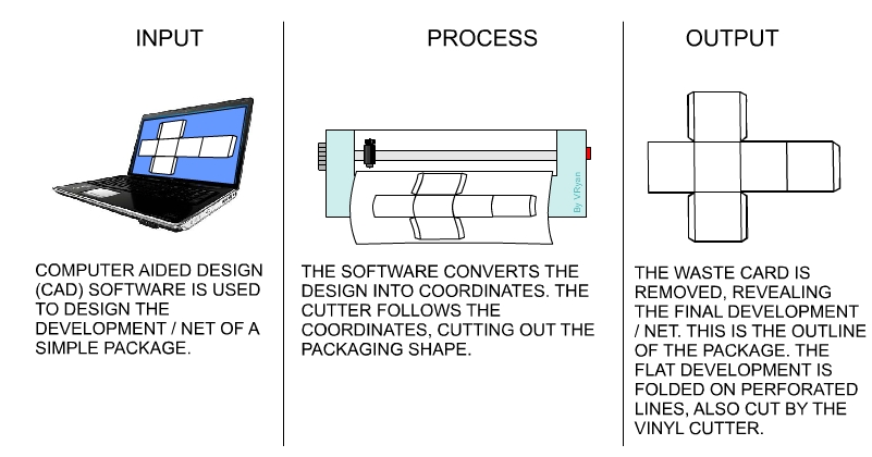
In industry packages are manufactured by machines. They are first designed on
a computer system using COMPUTER AIDED DESIGN software (CAD). A net /
development can be drawn more accurately by CAD software and also checked, with
faults can be corrected before any material is cut, Small companies use software
such as Techsoft 2D design, Coral Draw or other specialist software.
The software is used to control the cutting equipment.
A company called ‘Roland’ manufacture a range of machines that are computer controlled. They are capable of cutting out accurate nets and even scoring the fold lines, making it easy to fold the net together. A simplified version of one of these machines is seen below.
Roland produce a series of machines called STIKA machines. These are
basically used for cutting out adhesive backed lettering for signs and logos
(Material called 'sticky backed vinyl'). However, larger versions can be used to
cut out nets / developments from a range of card. The small hardened steel
cutter is held firmly in a tool holder. The tool holder moves up and down a
slide, following the design. The paper/adhesive laminate is fed into the machine
automatically. As the tool holder moves the cutting tool is pressed into the
material, cutting the desired shape.
These machines are suitable for cutting small numbers of developments/ nets.
4. The computer (including software), vinyl cutter and manufactured package, can be viewed as a Systems Diagram, see below. Systems diagrams are divided into three aspects/stages - INPUT - PROCESS - OUTPUT. The systems diagram below, describes what happens at each stage, from the design to manufacture of a simple package.