DRAWING TECHNIQUES USED BY DESIGNERS
AN INTRODUCTION
V. Ryan © 2010
| Designers and architects use a range of drawing techniques, to sketch and draw design ideas. A designer must master a variety of drawing techniques in order to be successful in their competitive world. The following drawing techniques are often used by Product Designers: | |
| Isometric Drawing, including
free hand isometric. Perspective Drawing. Flow Charts. Orthographic Projection. Computer Aided Design. Prototypes. Mood Boards. |
|
| Drawing techniques / skills allow the designer to communicate his/her ideas to customers/clients and consumers, so that they are clear and easy to understand. Presenting a design by using appropriate drawing and presentation techniques will ultimately lead to good business. After all, who would pay a designer who had difficulty presenting his / her design ideas? | |
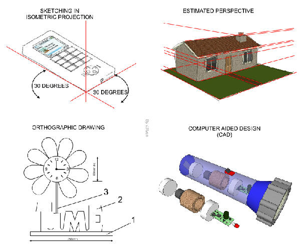
| A selection of drawing styles/techniques are seen below. All or some of these techniques are used by designers, during the design of a product. |
ISOMETRIC DRAWING AND DESIGNERS
V. Ryan © 2010
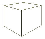
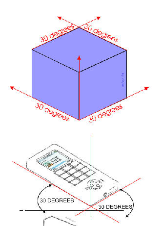
| Isometric drawing is way of presenting designs/drawings in three dimensions. In order for a design to appear three dimensional, a 30 degree angle is applied to its sides. The cube opposite, has been drawn in isometric projection. |
 |
| FREE HAND SKETCHING IN
ISOMETRIC: Designs drawn in isometric projection are normally drawn precisely using drawing equipment. However, designers find ‘free hand’ sketching in isometric projection useful. The mobile phone / music player opposite, has been sketched in free hand isometric projection. It allows the designer to draw in 3D quickly and with a reasonable degree of accuracy. The design is still drawn at a 30 degree angle, although this is estimated, rather than drawn with graphics equipment. Limited colour/shade has been added to the menu of the phone. This means that the sketch is not presented entirely as a ‘plain’ design. These drawings are quick sketches, that allow the designer to put his / her thoughts down on paper rapidly. This helps him/her develop an idea or design concept quickly, without the need for complex drawings, at an early stage in the design process. In early meetings with a client, the designer can display 3D drawings of this type in order to ascertain if the design is developing the way the client wants. |
| Drawing in isometric projection,
normally means drawing very accurately using traditional drawing equipment.
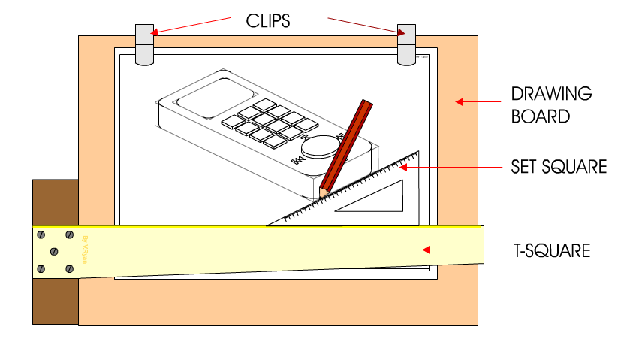
This includes using T-Square, set squares and measuring accurately. The isometric drawing seen opposite has been drawn precisely, using skills learned through hours of practice. When these skills have been developed, sketching in isometric becomes second nature. |
|
| EXPLODED ISOMETERIC PROJECTION | |
| Designers
use ‘exploded’ views, often drawn in isometric projection, to show parts of
products that are hidden from sight. For example, all the parts of the pen,
drawn below, can be seen because it has been taken apart using the drawing
technique called 'Exploded Isometric Projection'. With exploded isometric projection, all the parts are in line with each other, along a centre line. This is drawn precisely through the centre of the product being drawn. With a normal isometric drawing, all the parts are in their assembled positions. This means that vital hidden detail cannot be seen. |
|
 |
|
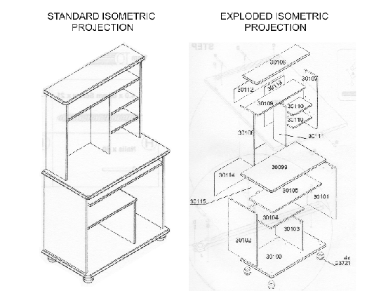
| Designers also use exploded views to explain their designs to clients/customers and manufacturers. Furthermore, exploded views of products are often supplied to customers, who in turn assemble the product. A good example of this is 'knock down' furniture. When the flat pack is opened, an instruction sheet or booklet explains how the furniture is assembled, often in the form of isometric exploded views. | |
| The drawings
seen below, were supplied with an instruction booklet. They are two of
numerous diagrams drawn in isometric projection. They help explain how the
cabinet and all its component parts are assembled, to form the finished
product. These are accurate drawings constructed by a designer, that explain how the product he/she has designed is assembled. |
|
 |
THE DESIGNER AND PERSPECTIVE DRAWING
V. Ryan © 2007 - 2010
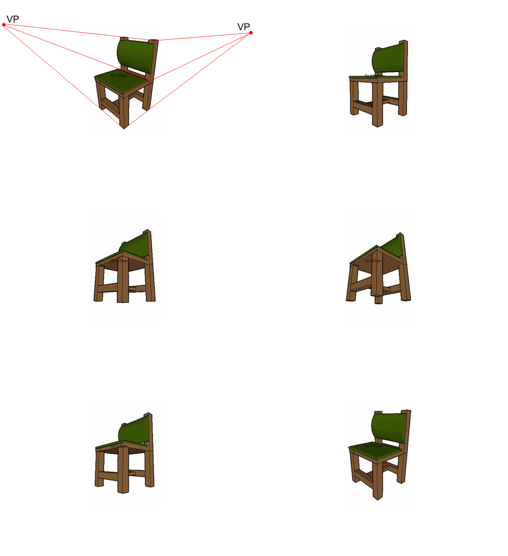
| A good example is seen opposite. The chair has been drawn using two point perspective. This means that the design is presented in a 3D format. If the vanishing points are moved to an alternate position, the chair can be viewed from a different angle. | |
| A complex design such as the interior of a room can be presented through the use of perspective drawing. The interior design opposite, is drawn in single point perspective and has been colour rendered to give a realistic finish. | |
| A designer, such as an architect, can use perspective to quickly present an idea. The quick sketch of the single storey house has been drawn in estimated perspective and took minutes to complete. However, it provides enough basic detail to allow an architect to explain an initial idea to a customer/client. The idea can be discussed and altered to suit the customer requirements. | |
| If a more detailed version is required, a colour rendered estimated perspective drawing can be shown to the customer/client. | |
|
SINGLE POINT PERSPECTIVE Perspective is a versatile drawing technique that designers use in a variety of ways. It is probably the most realistic way of drawing a 3D product / object. |
|
|
|
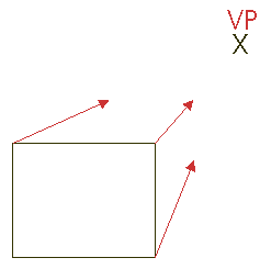
1. Draw one side of the cube and select a vanishing point (marked with an 'X'). |
|
|
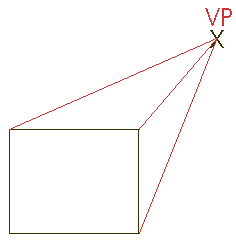
2. Draw very faint lines from each corner to the vanishing point. |
|
|
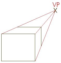
3. Draw horizontal and vertical lines for the 'back of the cube. |
|
|
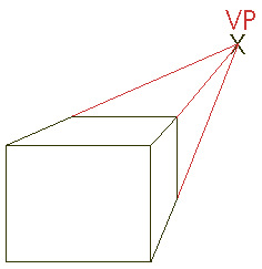
4. Go over the faint perspective of the cube so that the lines that make up the cube are dark and sharp. |
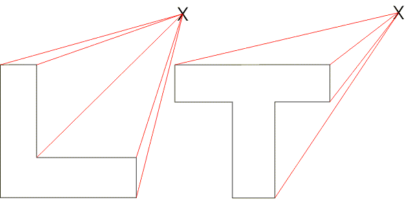
| Try completing the drawings of L-shapes and
T-shapes in single point perspective:
|
|
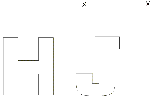
| Try completing the drawings of H-shapes and
J-shapes in single point perspective:
|
|
|
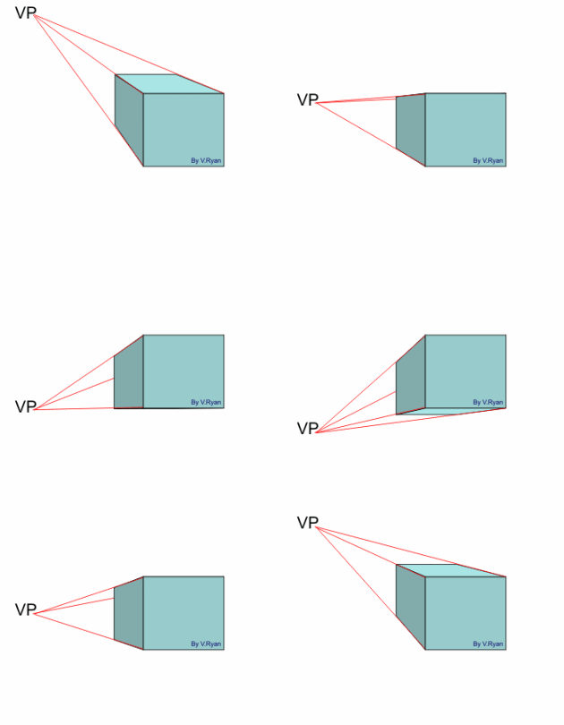
Altering the position of the VP changes the view of the object being drawn. For example, to look down at the top of the object the vanishing point must be above. However, to look up at the object the vanishing point must be below . |
|
|
PDF FILE - CLICK HERE FOR PRINTABLE EXERCISE |
|
|
|
|
|
Moving the VP to the left or right of the object will allow the sides to be seen. If the VP is placed directly behind the object then only the front will be seen. |
|
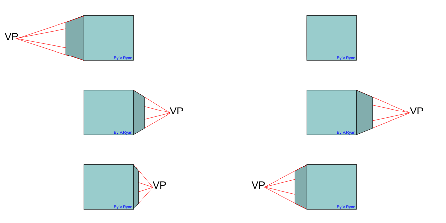 |
|
|
The animation of the chair displayed below emphasises the importance of positioning the vanishing point carefully. This chair is drawn with two vanishing points (this is called two point perspective). When the VPs are above the chair the view is also from above, looking downwards. However, when the VPs are moved below the chair the view also changes so that we are know looking from underneath. |
|
 |
|
|
TWO POINT PERSPECTIVE (1)
|
|
|
|
|
|
PDF FILE - CLICK HERE FOR EXERCISE BASED ON TECHNIQUE SHOWN BELOW |
|
| Perspective is a realistic way of drawing objects in 3D. We have already looked at single point perspective, two point perspective using two vanishing points and when an object is drawn in this way it is even more realistic than if it were to be drawn with a single vanishing point. | |
|
|
The cube apposite is drawn with two vanishing points and as a result the sides look as if they are slowly fading away into the distance. Two vanishing points gives this 'feel' to a drawing. |
|
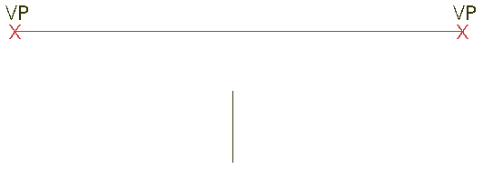
STAGE ONE: Mark two vanishing points on the paper and faintly draw a line between them - this is called the horizon line. Then draw one side/edge of the cube beneath the horizon line and in the centre between the vanishing points. |
|
|
|
|
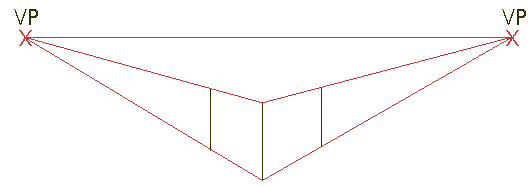
| STAGE TWO: Draw faint lines from the ends of the edge of the cube to the vanishing points | |
|
|
|
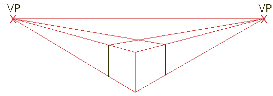
| STAGE THREE: Draw two more edges of the cube so that two sides of the cube can be clearly seen. | |
|
|
|
| STAGE FOUR: Draw faint guidelines from the ends of these lines to either vanishing point. | |
|
|
|
|
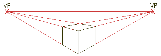
STAGE FIVE: Use a fine black pen to draw over the outline of the cube. Add shade - look at the colouring techniques discussed earlier. |
|
|
|
|
TWO POINT PERSPECTIVE (2)
|
|
|
|
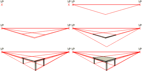
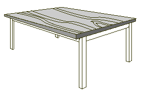
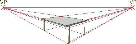
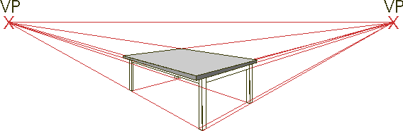
In this example a simple kitchen table is drawn in two point perspective. This is much more difficult compared to the single point perspective shown earlier. This time it is very important to project guidelines towards both vanishing points. The stages are outlined below. |
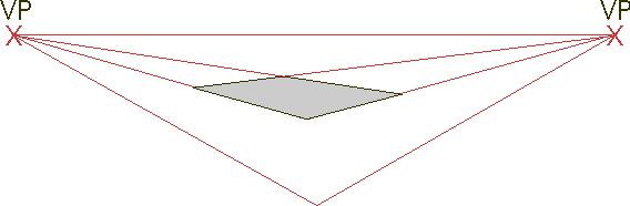
| STAGE ONE: Mark both vanishing points and start drawing faintly - the table top. | |
|
|
|
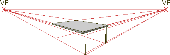
| STAGE TWO: Add thickness to the table top remembering to project all lines to the vanishing points. Add the front legs. | |
|
|
|
| STAGE THREE: Add one of the back legs. | |
|
|
|
| STAGE FOUR: Add the final leg and any other detail such as shade/colour. | |
|
|
|
|
Sometimes, in order to produce a realistic drawing the
vanishing points need to be positioned beyond the edge of the paper. This is
estimated perspective. When drawing, the guidelines they are projected back
to imaginary vanishing points. |
|
| PDF FILE - CLICK HERE FOR PRINTABLE VERSION OF QUESTION SHOWN BELOW | |
 |
|
THE DESIGNER AND ORTHOGRAPHIC DRAWING
V. Ryan © 2010
| An orthographic drawing,
sometimes called a working drawing, is usually the last drawing produced
by a designer. It normally has three accurate views of a product, a front
view, side view and plan view. Dimensions (measurements) are also drawn on
each view, ensuring the manufacturer can make the product to the precise
size and the designers requirements. A parts list is also included. This
has the precise measurements for every part of the product and includes
details such as materials and finish. A working drawing is required if manufacturing is to take place |
|
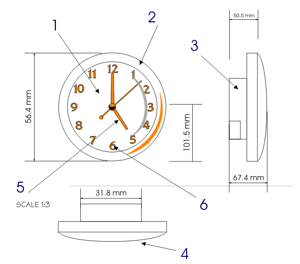
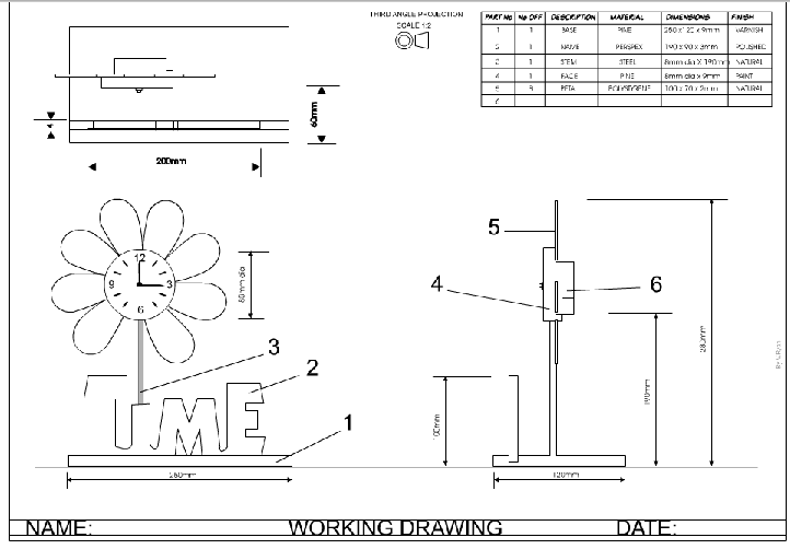
| The working drawing
seen below is for a clock. It has been drawn in a system called Third
Angle Orthographic Projection, a world standard for this type of
presentation. It should be possible for a designer based in the UK, to draw an working drawing of a product and for it to be manufactured in another country, by using only the orthographic drawing. This is called ‘Remote Manufacture’. The orthographic drawing should be accurate and include all the information required for manufacturing. Designers often use this process for the design and manufacture of products. |
|
| ORTHOGRAPHIC DRAWING - HOW IT IS PRESENTED TO A MANUFACTURER | |
 |
|
| Designers often use remote manufacturing, in an attempt to keep costs low. Designers also produce working drawings so that prototypes can be manufactured, and then tested. This leads to improvements being made to the product. Working drawings are usually produced using CAD, although skilled designers still draw them be hand, at least in the early stage of the designing process. Designers find sketching in orthographic projection very useful. | |
| Information found on a working
drawing / orthographic drawing: All necessary views required for manufacturing. All the necessary measurements (called dimensions). A standard format for working drawings. A parts list which includes all the information needed to make each part of the product. |
|
INTRODUCTION TO THIRD ANGLE ORTHOGRAPHIC DRAWING
V. Ryan © 2010
| PDF FILE - CLICK HERE FOR PRINTABLE WORKSHEET |
| PDF FILE - CLICK HERE FOR PRINTABLE WORKSHEET TWO |
| Orthographic drawing is
a way of drawing a three dimensional object. Normally the object is drawn
as three separate, related views - Front View, Side View and Plan View.
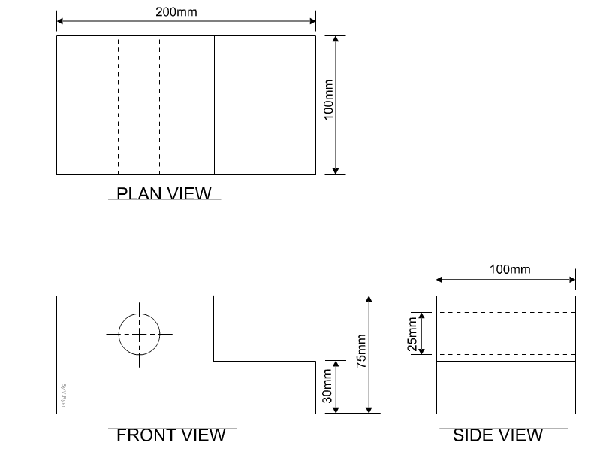
The example below shows a simple shaped block, with a hole drilled all the way through. The front view, is a drawing of the block, as if you are looking directly at the front of the object. The side view, is a drawing of the block, when it has been rotated so that one of its sides is now directly in view. The plan view, is a ‘birds eye’ view, from above. Dotted lines represent ‘hidden detail’. In this case they represent the hole, through the block/object. |
| The front, side and plan
views are arranged in the positions shown below. They must be drawn
accurately. Draw the front view first, followed by the side view. The plan view is drawn directly above the front view. Note, a 45 degree line allows the projection of the side view to the plan view. |
| Dimensions (measurements) are added to the completed views. Usually six dimensions are added. This enables anyone looking at the orthographic drawing, to work out the overall size of the object. More dimensions can be added if necessary. Dimensions are drawn on each of the views. |
 |
THIRD ANGLE - ORTHOGRAPHIC PROJECTION
FURTHER EXPLANATION
V. Ryan © 2002 - 2010
|
Click here for an Introduction to Third Angle Orthographic Drawing Click here for Third Angle Orthographic Drawing - an Example |
|
|
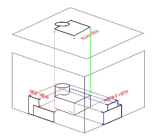
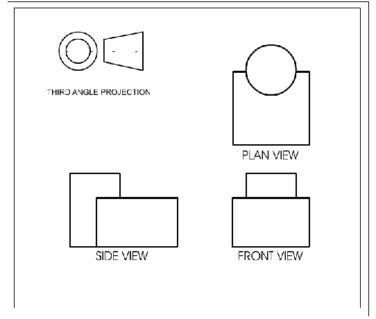
Orthographic Projection is a way of drawing an object from different directions. Usually a front, side and plan view are drawn so that a person looking at the drawing can see all the important sides. Orthographic drawings are useful especially when a design has been developed to a stage whereby it is almost ready to manufacture. IMPORTANT: There are two ways of drawing in orthographic - First Angle and Third Angle. They differ only in the position of the plan, front and side views. Below is an example of third angle projection. |
|
|
An L-shaped object. The Plan View of the L-shape is drawn as a 'birds eye' view, a view from above. The Front View is drawn as if stood in front of the L-shape. The Side View is drawn as if stood at the side. |
|
| The correct position of each view is shown below. They have been drawn very accurately, using T-Squares and set squares. | |
 |
|
|
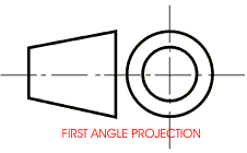
Carefully study the symbols shown below. Normally when drawing in first or third angle projection a symbol is drawn which clearly shows which angle of projection has been used. |
|
|
|
|
FIRST ANGLE - ORTHOGRAPHIC PROJECTION
V. Ryan © 2002 - 2010
|
Orthographic Projection is a way of drawing an 3D object from different directions. Usually a front, side and plan view are drawn so that a person looking at the drawing can see all the important sides. Orthographic drawings are useful especially when a design has been developed to a stage whereby it is almost ready to manufacture. IMPORTANT: There are two ways of drawing in orthographic - First Angle and Third Angle. They differ only in the position of the plan, front and side views. Below is an example of First Angle projection. |
||
|
Opposite is a simple L-shape, drawn in three dimensions. The front, side and plan views have drawn around the 3D shape. However this is not the correct way of drawing them as they are not in the right positions. |
||
|
The correct method of presenting the three views, in first angle orthographic projection is shown below. The drawing is composed of a front, side and plan view of the L-shaped object. The first drawing is the front view (drawn looking straight at the front of the L-shape), the second is a drawing of the L-shape seen from the side (known as side view) and last of all a drawing from above known as a plan view. The red lines are faint guidelines and they are drawn to help keep each view in line, level and the same size. Please Note! This is an example of first angle orthographic projection (as used mainly in Europe). There is another type called third angle which is used by countries such as the USA. The front, side and plan views are in different positions |
||
|
THE SIDE VIEW |
||
|
Imagine standing directly at the side of the L shape. |
||
|
THE FRONT VIEW |
||
|
Now imagine standing directly in front of the L-shape, the drawing opposite shows exactly what you would see. |
||
| THE PLAN VIEW | ||
| The plan view is a view seen directly from above. Some people call this a birds eye view. | ||
DIMENSIONS
V. Ryan © 2002-2008
|
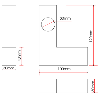
It is very important to add dimensions (measurements) when drawing accurate orthographic or working drawings. An orthographic drawing is usually the last drawing before manufacture and so dimensions must be clearly presented and understood. Dimensions can also be applied to simple sketches and designs as they help anyone looking at these to understand the overall size or scale. However, dimensions are usually drawn in a particular way and some examples are shown below. |
|
| PDF FILE - CLICK HERE FOR PRINTABLE EXERCISE BASED ON WORK SEEN BELOW | |
|
The drawing below is in first angle orthographic projection |
|
|
|
|
|
Normally at least six dimensions are placed on a working drawing. They are drawn quite faintly except for the arrow heads and the numbering which are darker. The arrow head must be sharp but above all the dimensions must be accurate. |
|
|
|
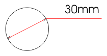
This type of dimension is normally used for a circle. The unusual symbol (zero with a line through it) is simple way of writing diameter. |
|
|
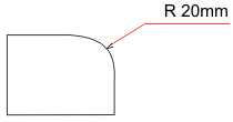
Curved corners can be dimensioned like this. 'R' means radius (the compass setting). |
|
|
Example of a standard dimension. The dimension is drawn quite faint with the exception of the number and arrow heads. |
|
|
If a measurement is 9mm or smaller the dimension is drawn in a slightly different way. The arrows point inwards, towards the number. |
|
THE SOLUTION - WORKING DRAWING FIRST ANGLE PROJECTION V. Ryan © 2001-2008
|
|
|
A working drawing is the final ‘constructed’ drawing,
produced as part of the design process. It usually consists of a front,
side and plan view of the solution. Sometimes there are two views but this
depends on the complexity of the solution. Dimensions are added so that
any person using the working drawing can manufacture the design. Usually
there are at least six dimensions but you can add as many as you feel are
required in order for the manufacturer to make your solution. |
|
|
|
|
|
(WORKING DRAWING SEEN ABOVE IS DRAWN IN FIRST ANGLE PROJECTION) |
|
PARTS LIST |
||||||||||||||||||||||||||||||||||||||||||||
|
A ‘Parts List’ is a very important feature of the working
drawing as all the parts are listed, with measurements. The materials used
are also mentioned as well as the finish applied to the individual pieces. |
||||||||||||||||||||||||||||||||||||||||||||
|
||||||||||||||||||||||||||||||||||||||||||||
|
Try to complete the parts list above - you may need to estimate some measurements |
||||||||||||||||||||||||||||||||||||||||||||
|
FURTHER INFORMATION |
||
| The example shown below has a back view, side view and plan view of a pine box with a perspex lid. The box contains an educational toy.. The front view is not needed because it is plain, with no detail. The back view has hinges and consequently it is important that it is drawn. The working drawing (seen below) is accurate and detailed so that a suitably skilled person could manufacture the design from the information shown. | ||
| 1. The working drawing should be precise and
drawn to a scale. The drawing opposite is half the size of the solution, the
scale is 1:2. If the drawing was a 3rd the size of the original then the
scale would be 1:3. 2. Usually there are at least six dimensions but you can add as many as you feel are required in order that the precise size of your design can be determined by anyone reading the drawing. 3. Use a 2H pencil or a fine black pen for the final outline, as the drawing will then stand out. 4. Draw the measurements (dimensions) very carefully. Some example dimensions are shown below. They should be drawn with a sharp 2H pencil. |
||
|
|
||
|
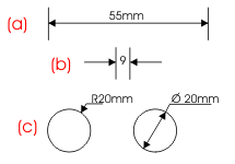
The arrows and the written measurement should be dark and
the rest of each dimension should be faint. Dimensions are normally drawn as
shown in (a) although dimensions under 9mm should be drawn as shown in (b).
Diameters and radii are drawn as shown in (c). |
||
|
|
||
|
SUGGESTIONS |
||
|
A. Consider carefully the
type of views you need to draw (front, side, plan etc...) and draw a rough
version. |
||
THE DESIGNER AND ORTHOGRAPHIC DRAWING - SECTIONAL VIEWS
V. Ryan © 2007 - 2010
| Sectional views are an aspect
of orthographic drawing. A designer can use this technique to show the
interior of a design. For example, the ‘magnetic force torch’, shown
below. This is a modern rechargeable torch and it is important for the
manufacturer to be able to see the internal parts. A drawing like this
also helps the designer visualise the way the parts go together to form
the final product. The 3D drawings below are NOT orthographic. However, they are drawn to illustrate what a sectional view actually is. A sectional view is a view of a product as if part of it has been cut away. In this case the a cut has been made right down the centre of the torch, allowing the internal parts to be seen. |
|
| ANIMATION - SECTIONAL VIEW | |
| An orthographic drawing of the torch is drawn below. It is comprised of a front view and a sectional side view. The centre line labelled ‘AA’ on the front view, shows where the ‘cut’ through the torch has been made. Any surfaces that have been cut have ‘hatched’ lines. This sectional view reveals the interior of the torch, making possible for the manufacturer to understand how the torch and its parts go together. | |
 |
THE DESIGNER AND COMPUTER AIDED DESIGN
V. Ryan © 2010
| Computer Aided Design (CAD) is a vital tool for a Product Designer. CAD software allows a designer to quickly produce 3D images/designs. The design can then be rotated, colour rendered and analysed/evaluated. Then it can be improved. Software such as SketchUp, provided by Google, is ideal for a young designer or a professional. | |
| The model below has been generated using CAD (Computer Aided Design) software. The furniture has been drawn individually and placed inside the computer generated room. The room can be rotated to almost every possible angle. This design can be shown to potential customers or a client and changes made according to his/her likes and dislikes. This saves time and money as the model can be altered using the software, which is far more efficient than making a real model using materials. | |
| The phone shown below has been
designed using the same CAD software. The client (an international
communications company) have been asked how they would like it changed so
that it is exactly what they want for there retail outlets. The client’s representatives have tested the computer model on a selection of potential customers (called a Focus Group). They have recommended changes and these will be applied to the computer generated image. It will then be tested for a second time, before a prototype is manufactured at great expense. |
|
| The technologically
advanced torch shown below has been modelled so that the internal electronic
parts can be seen. Making an real model to display this type of information
would be very expensive. However, a computer generated model can be animated
to show how the parts fit together. the outer casing can be made to look
either transparent or translucent at a click of a mouse. In this case, a computer model has major advantages compared to a real model, manufactured from actual materials. |
|
THE DESIGNER AND PROTOTYPES
V. Ryan © 2010
| A designer will make a number of prototypes before deciding on a final version of a product. There are many reasons for this and some are written below. (Click here for information on modelling materials). | |
| 1. Unlike a computer model, a
prototype can be physically handled by the designer, a design team and
potential customers. 2. Making a scaled prototype allows the designer / manufacturer to work out the method of construction/manufacture. This cannot be done accurately when using CAD. 3. Making a prototype allows the manufacturer to determine the ‘flow’ of production on a production line, in a factory. 4. Design errors are often detected when making a scaled model / prototype. Often design or manufacturing problems can be solved at this stage. 5. The designer can display the prototype at meetings and there is no need to rely on an expensive computer system. 6. A prototype can be tested by potential customers and focus groups. 7. A prototype can be used as an integral part of a questionnaire. A computer model is not as effective as a real life object, as it cannot be handled. |
DESIGNERS AND MOODBOARDS
V. Ryan © 2010
| A moodboard is a collection of pictures / images / text, related to a design theme. The example moodboard seen below, is based on the theme ART DECO. It has a includes a number of images that relate directly to the period 1924 to 1940, a period dominated by the art movement called Art Deco. | |
 |
| Moodboards are often used by
designers as a method of initial research into a product or design. A
moodboard is often the first piece of design work, at the begining of a
project. For instance, if a designer was asked by a client to design a piece
of furniture for an Art Deco theme room, he/she may start with researching
images and pictures from that period. The Art Deco moodboard above, provides an insight into the style of design of that era. Art Deco is an international decorative arts movement, most popular between the years 1924 - 1940. It is a style of drawing, that relies on bold designs, clear lines, vibrant colours and patterns. Geometric shapes and intense colour schemes are prominent. Art Deco’s main characteristics are derived from the various painting styles of the early twentieth century, ranging from Cubism to Italian Futurism. Art Deco is usually associated to the architecture of the 1930s and speed and luxury. Recently it has seen a revival. This type of research helps focus the mind of the designer, ensuring that he/she does not stray from the theme, keeping to the style of design associated with the style demanded by the client. |
|
| The items seen below have been designed by designers, with a clear instruction from their clients, to produce Art Deco related products. The moodboard has played on important role, as the products clearly display Art Deco features, in terms of shape and form. |
A client may put together a moodbaord for a designer. The aim is for the designer to analyse the moodboard and discuss it in detail with the client. This helps the designer identify the style that the client wants to persue for their product. It also helps the designer develop specific skills and then apply them to the product, as it is designed. For instance, the Art Deco moodboard clearly shows the shapes, style of line/curves and colour / pattern schemes, that fit that era of design. Deviating from this style would inevitably lead to a product that may not fulfil the clients needs or requirements.
DESIGNER INSPIRATION - MOOD BOARDS
V. Ryan © 2011
| PDF FILE - CLICK HERE FOR PRINTABLE WORKSHEET | |
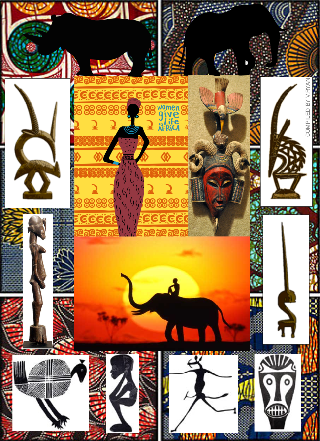
| Designers often find inspiration in images, pictures, photographs and symbols. A moodboard is a collection of pictures / images / text, related to a design theme. A moodboard is often used by a designer to help them design / style products. They are also used by designers as a form of initial research into a product or design. For instance, if a designer was asked by a client to design a piece of furniture for an African themed room, he/she may start by putting together an African moodboard (as see below). Furniture designs are then developed from the images, patterns and colours, found in the moodboard. | |
| AFRICAN MOODBOARD COMPOSED OF PICTURES, SYMBOLS, PATTERNS AND COLOURS | |
 |
|
| AFRICAN THEMED FURNITURE - MOODBOARD INSPIRED | |
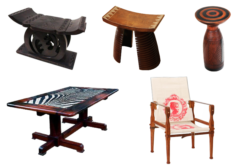
| An African symbol, seen in the moodboard, has been simplified and then used to form the legs of a table. Natural African woods such as African Hyedua, African Padauk or African Mahogany have been selected as the main materials. | |
| A typical African pattern, from a piece of textile/fabric, has been applied to a ceramic tile. The tiles are then arranged to form the surface of the table. The final result is an African themed table, manufactured from African natural woods, based on African symbols and patterns. | |
| AFRICAN THEMED BOOKSHELF | |
| The African themed bookshelf, is based on the Africa figure seen in the moodboard. The original engraving has been simplified. The red/orange colours are also taken from the photograph of the African sunset (seen in the moodboard) , resulting in a modern, bright version of an African bookshelf. It is manufactured from cast iron and finished with paint. | |
| AFRICAN THEMED CHAIR - MOODBOARD INSPIRED | |
| The chair seen below is based on an image seen in the moodboard. The image has inspired the shape / form of the chair. The original shape has been stretched and simplified. African natural wood has been used to manufacture the final chair. Orange cushions have been added, the colour being taken from the photograph of the African sunset. | |
| SAMPLES OF AFRICAN INSPIRED FURNITURE | |
 |
|
INSPIRATION / MOODBOARDs AND MOTIFS
V. Ryan © 2011
| PDF FILE - CLICK HERE FOR PRINTABLE WORKSHEET | |
| A motif is a repetitive pattern or
shape, often applied to clothes, carpets, cups, lamp shades, and a range
of other products. Designers often use natural forms to help inspire a
design of motifs. The Rain Forest Trust logo (seen opposite) has been developed from a frog found in the rain forest. In the same way, designers developing a motif (repeated pattern), often look for inspiration in pictures / images from the natural world. |
|
 |
|
When you attempt a design project, especially if you are on the Graphic Products course, it is very important that you display a full range of graphic techniques. These techniques are divided into two areas; colouring techniques and drawing techniques. (Use techniques that are not listed if they are appropriate). Tick the columns on the right as you work through your project.
| COLOURING TECHNIQUES PENCILS 2H pencils - Use ordinary pencils to draw and sketch. Colouring pencils - Use pencils to colour drawings and to draw the outline of designs. CARD Overlays/backing - Use card on top of card, you could glue together two different pieces of card and then place a design brief or something similar on the top. The card will be a backing. Colour placed on card - Try shading card with a coloured pencil, use a dark colour of card and shade it with a light shade of pencil. Use the result to back text/writing. Composite drawings - See the examples in class. Drawings constructed from different colours of card can be quite striking. FELT PENS Brush and fine line pens - see
craft knife project Line Shading - see flat
surface examples |
DRAWING TECHNIQUES draw designs that are ‘in bits’, or ‘taken apart’ so that all the parts
of the design can be seen easily. Computer Generated Systems Model (Spreadsheets)
|