Jigs & Fixtures
Entre las herramientas, un apartado especial merecen aquellos dispositivos o
ayudas fabricadas para una determinada tarea, y, muchas veces, por la propia
persona que va a ejecutarla. Normalmente se trata de herramientas sencillas con
pocos o ningún mecanismo y que sirven para sujetar las piezas mientras se las
somete a algún tratamiento o proceso, aunque pueden servir para labores más
sofisticadas. A este tipo de útiles que sirven de plantilla, sujección, medida o
comparación y que comparten la propiedad de haber sido diseñados o 'hechos en
casa' se los suele conocer por los términos gálibo, gabarito o, en inglés, jig.
La eficacia del trabajo en el taller y la calidad de éste depende muchas veces
del conocimiento, la imaginación y la habilidad para fabricar estos útiles.
Made-on-shop tools are usually known as 'jigs'[1]. A jig's primary purpose is
to provide repeatability, accuracy, and interchangeability in the manufacturing
of products, and also to saving labour and facilitating less skilled labour.
From here you can find the description of some of them which have been
helpful for other musical instrument builders.
[1] Properly speaking, a jig or template is a type of device
used to control the location or motion of another tool. A jig is often confused
with a fixture; a fixture holds the work in a fixed location. The device which
guides the tool is called jig and the device which holds the job in position is
called fixture.
Jigs and Fixtures:
Some machining operation are so simple’ which
are done quite easily, such as turning, the job is held in position in the
chuck and turning operation is done easily. No other device is required to
hold the job or to guide the tool on the machine in such an operation. But
some operations are such type in which the tool is required to be guided by
means of another device and also some jobs are of such forms which are
required to be held in position on the machine by means of another device.
The device which guides the tool is called jig
and the device which holds the job in position is called fixture.
Jigs and fixtures are special purpose tool
which are used to facilitate production (machining, asslembling and inspection
operations), when work piece is based on the concept of interchangeability
according to which every part will be produced within an established
tolerance. Jigs and fixtures provide on means of manufacturing interchangeable
parts since they establish a relation with predetermined to tolerance between
the work and cutting tool. They eliminate the necessity of a special set up
for each individual park. So’ A jig is may be de-fined as a device which hold
and position the work; locate or guides the outing tool relative to the work
piece and usually not fixed to the m/c table. It is usually lightly in
construction.
A fixture is a work holding device and position
the work; but doesn’t guide ‘locate or position the cutting tool’ the setting
of the tool is done by machine adjustment and a setting blocker using slip
gauges. A fixture is hold or clamp-ed to the machine table. It is usually
heavy in construction. Jigs are used on drilling , reaming , tapping and
couter boring operations , while fixtures are used in connection with turning
, milling , grinding , shaping , planning and boring operations.
The use of jig and fixture makes possible more
rapid and more accurate manufacturing at a reduction of cost.
Uses of Jigs and Fixtures:
- Jigs and fixtures are
used to reduce the cost of production as there use elimination being out work
and setting up of tools.
- To increase the
production.
- To assure the high
accuracy of the parts.
- To provide for
interchangeability.
- To enables heavy and
complex shaped parts to be machined by holding rigidly to a machine.
- To control quality
control expenses.
- Less skilled labor.
- Saving labor.
- There use partially
automates the machine tool.
- Improve the safety at
work, thereby lowering the rate of accidents.
Jigs
The most-common jigs are drill and boring
jigs. These tools are fundamentally the same. The difference lies in the
size, type, and placement of the drill bushings. Boring jigs usually have
larger bushings. These bushings may also have internal oil grooves to keep
the boring bar lubricated. Often, boring jigs use more than one bushing to
support the boring bar throughout the machining cycle.
In the shop, drill jigs are the most-widely
used form of jig. Drill jigs are used for drilling, tapping, reaming,
chamfering, counter boring, countersinking, and similar operations.
Occasionally, drill jigs are used to perform assembly work also. In these
situations, the bushings guide pins, dowels, or other assembly elements.
Jigs are further identified by their basic
construction. The two common forms of jigs are open and closed. Open jigs
carry out operations on only one, or sometimes two, sides of a work piece.
Closed jigs, on the other hand, operate on two or more sides. The
most-common open jigs are template jigs, plate jigs, table jigs, sandwich
jigs, and angle plate jigs. Typical examples of closed jigs include box
jigs, channel jigs, and leaf jigs. Other forms of jigs rely more on the
application of the tool than on their construction for their identity. These
include indexing jigs, trunnion jigs, and multi-station jigs.
Specialized industry applications have led to
the development of specialized drill jigs. For example, the need to drill
precisely located rivet holes in aircraft fuselages and wings led to the
design of large jigs, with bushings and liners installed, contoured to the
surface of the aircraft. A portable air-feed drill with a bushing attached
to its nose is inserted through the liner in the jig and drilling is
accomplished in each location.
Fixtures
Fixtures have a much-wider scope of
application than jigs. These workholders are designed for applications where
the cutting tools cannot be guided as easily as a drill. With fixtures, an
edge finder, center finder, or gage blocks position the cutter. Examples of
the more-common fixtures include milling fixtures, lathe fixtures, sawing
fixtures, and grinding fixtures. Moreover, a fixture can be used in almost
any operation that requires a precise relationship in the position of a tool
to a workpiece.
Fixtures are most often identified by the
machine tool where they are used. Examples include mill fixtures or lathe
fixtures. But the function of the fixture can also identify a fixture type.
So can the basic construction of the tool. Thus, although a tool can be
called simply a mill fixture, it could also be further defined as a
straddle-milling, plate-type mill fixture. Moreover, a lathe fixture could
also be defined as a radius-turning, angle-plate lathe fixture. The tool
designer usually decides the specific identification of these tools.
Types Of Fixtures:
Milling Fixtures:
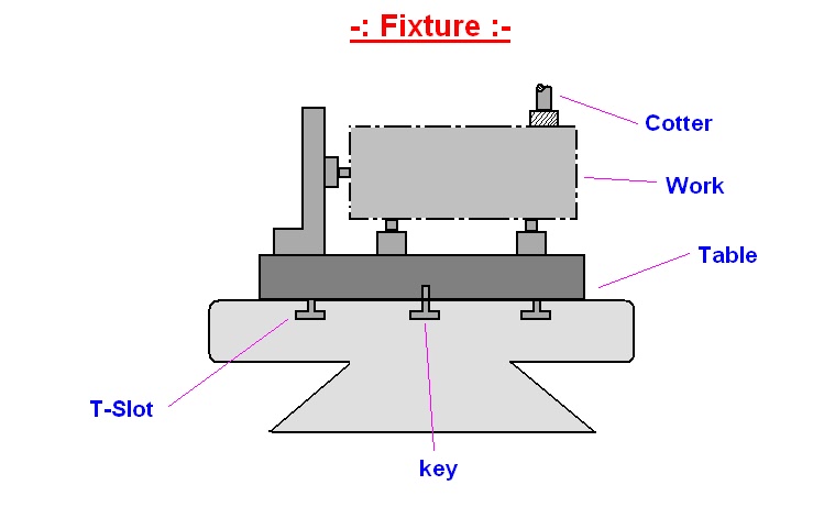
A Milling fixture is a work holding device
which is firmly clamped to the table of the milling machine. It holds the work
piece in correct position as the table movement carries it past the cutter or
cutters.
Essentials of Milling Fixtures:
1: Base:
A heavy base is the most important element of a
milling fixture. It is a plate with a flat and smooth under face. The complete
fixture is built up from this plate. Keys are provided on the under face of
the plate which are used for easy and accurate aligning of the fixture on the
milling machine table. By inserting them into one the T slot in the table.
These keys are usually set in keyways on the under face of the plate and are
held in place by a socket head cap screw for end key. The fixture is fastened
to the machine table with the help of two T bolts engaging in T slots of the
work table.
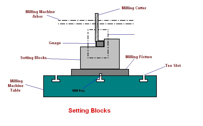
2: Setting Blocks:
After the fixture has been securely clamped to
the machine table , the work piece which is correctly located in the fixture ,
has to be set in correct relationship to the cutters. This is achieved by the
use of setting blocks and feeler gauges. The setting blocks is fixed to the
fixture. Feeler gauges are placed between the cutter and refrence planes on
the setting block so that the correct depth of the cut and correct lateral
setting is obtained. The block is made of hardened steel and with the refrence
planes(feeler surfaces) grooved. In it correct setting , the cutter should
clear the feeler surfaces by at least 0.08cm to avoid any damage to the block
when the machine table is moved back to unload the fixture. The thickness of
the feeler gauge to be used should be stamped on the fixture base near the
setting block.
3: Locating and Clamping Elements:
The same design principles of location and
clamping apply for milling fixtures have been discussed above.
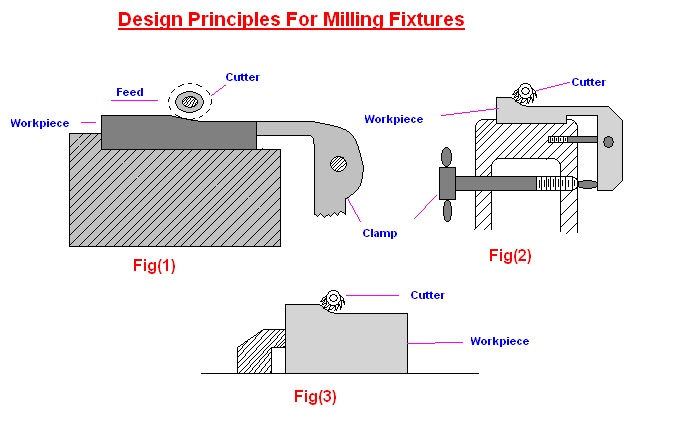
Some Design Principles for Milling
Fixtures:
1: Pressure of cut should always be against the
solid part of the fixture(fig a).
2: Clamps should always operates from the front
of the fixture (fig B)
3: The work piece should be supported as near
the tool thrust as possible(fig c)
Design principles Common to jigs and fixtures:
There are some principles which are useful to design jigs and fixtures.
1: Rigidity:
Jigs and fixtures should be sufficiently stiff to secure the preset accuracy
of machining.
2: Fool proofing:
It can be defined as “ the incorporation of design feature in the jig or
fixture that will make it possible to lead the work into jig and fixture, in
an improper position , but will not interfere with loading and unloading the
work piece.” There are many fool proofing devices , such as fooling pegs,
blocks or pins which clears correctly position parts but prevent incorrectly
loaded parts from entering the jig and fixture body.
3: Clearance:
Clearance is provided in the jig or fixture body
(A) to allow for any variation in component sizes specially casting and
forging.
(B) To allow for hand movements so that the work piece can easily placed in
the jig or fixture and removal after machining .
4: Burr Grooves:
A burr raised on the work piece at the start of the cut is termed a minor burr
and at the end of a cut is called a major burr. Jigs should be designed so
that the removal of the work piece is not obstructed by these burr for this
suitable clearance grooves or slots should be provided.
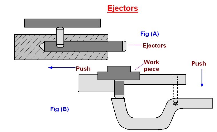
5: Ejectors:
The use of ejection devices to force the work piece out from the jig or
fixture is important in two positions.
(A) the work piece is heavy
(B) machining pressure
forces the work piece to the slides or based on the jig or fixture and the
pressure and oil or coolant fill will cause the work to strick and difficult
to remove on small jigs and fixtures , a pin located under the work will
remove the part radially.
6: Inserts:
To avoid any damage to fragile and soft work piece and also to the finished
surfaces of the work piece while clamping. Inserts of some soft material such
as copper, lead , fiber , leather , hard rubber and plastic should be fitted
to the faces of the clamps.
7: Design for Safety:
Jigs and fixtures must be safe and convenient in use, following are the some
Factors for the safety of worker working on jigs and fixtures.
(A): Sharp corner on the body of jig and fixture should be avoided.
(B): Sighting surfaces should be cleared.
(C): Bolt and nut should be inside the body of jig or fixture and not protrude
on the surface.
8: Sighting Surface:
Machining on the work piece must be clearly visible to the worker. He should
not be required to bend is neck for seeing the work piece or work surfaces.
9: Simplicity in design:
Design of the jig and fixture should be a simple one. A completed design
require a large maintenance. They should be easily to set , cheap in
manufacture.
10: Economical:
Jig and fixtures should be simple in construction, give high accuracy , be
sufficiently rigid and lightly weight. To satisfy these conditions an
economical balance has to be made.
Elements of Jigs and Fixtures.
Various elements of jigs and fixtures and their
details are follows.
1: Body 2: Locating devices
3: Clamping devices
4: Tool guide(jigs bushing)
1: Body:
The jig body is generally made of cost iron by
casting process or fabricated by welding together various slabs and bars of
mild steel. It may be heat treated to relief the stresses. Body is the most
prominent feature of the jig. Its main purpose is to support and house the
job.
The various jig body are follows:
(A):Plane Type Jig:
Plane type jig is the simplest type, it is used
when plane holes are to be drilled. It has either drill bushes for guiding the
tools or the holes without bushes.
(B): Channel Type Jig:
Channel type is made up from standard steel
channel section.
(C): Box type Jig:
Box type jig is used where a component requires
drilling in more than one plane and the jig is to be provided with on equilant
number of drill bush plates. One side of the box is fitted with a lid which
can be opened for inserting the component and for unloading it. It should be
made as light as possible.
(D): The Built Up Jig:
The built up jig used dowels and screws for
fabricating member welded type. Standard steel sections are used in it for the
limited numbers of details, which are secured by means of screws and dowels,
the locating pins and the blocks are positioned so that the greatest
dimensional variation of the work piece may be accommodated.
(E): Leaf Type Jig:
Leaf type jig is simple made from a block of
steel fitted with two adjustable locating screws and a spring loaded plunger.
It is used in case of measured large components where it may be both
unnecessary and construct a jig to hold the complete component , where madding
is purely confined to a local section of the work piece.
2:Locating Devices
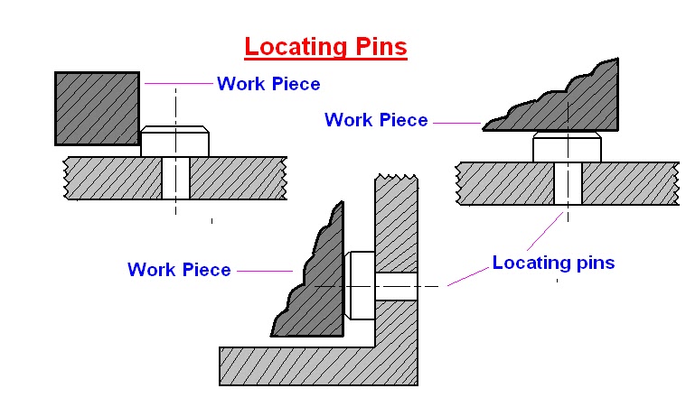
The pins of various design and made of hardened
steel are the most common locating devices used to locate a work piece in a
jig or fixture. The shank of the pin is press fitted or driven into the body
of jig or fixture. The locating diameter of the pin is made larger than the
shank to prevent it from being forced into the jig or fixture body due to the
weight of the work piece or cutting forces. Depending upon the mutual relation
between the work piece and the pin.
The pin may be classify as follows:
(A): Locating Pins:
When reamed or finally finished holes are
available in work piece, these can be used for locating purpose of the manner
as shown , these are two types of locating pins:
· Conical locating pins
· Cylindrical locating pins
(B): Support Locating Pins:
With these pins (also known as rest pins)
buttons or pads the work piece with flat surfaces supported at convenient. In
the fixed support pins the locating face is either ground flat or curved.
Support pins with flat head are usually employed and provided location and
support to machine surface, because more contact area is available during
location. It would insure accurate and stable location. The spherical head or
round head rest buttons are used for supporting rough surfaces (un machined
and cast surfaces) because they provide a point support which may be stable
under these circumstances. Adjustable type support pins are used for work
piece whose dimension can vary. For example sand casting, forging or
unmachined faces.
(C): Jack Pins:
Jack pins or spring pins are also used to
locate the work piece whose dimension are subjected to variation. The pin is
allow to come up under spring pressure or conversely is pressed down by the
work piece. When the location of the work piece is secured the pin is locked
in this position by means of locking screw.
Elements of jigs and fixtures:
3: Clamping devices:
If the work piece can not be restrained by the
locating devices or elements, it become necessary to clamp the work piece in
jig or fixture body. The most common example of clamping devices is bench
vice. The purpose of the clamping is to exert a pressure to press a work piece
against the locating surfaces and hold it there in a position to the cutting
forces. In bench vice the movable jaw of the vice exert force on the work
piece , their by holding it in correct position of location in the fixed jaw
of the vice.
The commonly used clamping devices are follows:
(A): Clamping Screws:
Clamping screws are used for light clamping.
Clamping screws are shown in fig.
(B): Hook Bolt Clamp:
This is very simple clamping device and is only
suitable for light work and where usual tip of the clamp is inconvenient. The
typical hook bolt clamp is shown.
(C): Bridge Clamp:
It is very simple and reliable clamping device.
The clamping force is applied by spring loaded nut.
(D): Heel Clamp:
These consists of a rusted plate, center stud
and heel. This trap should be strengthen at the point where the hole for the
stud is cut out, by increasing the thickness around the hole. The design
differ from simple bridge clamp in that a heel is provided at the outer end of
the clamp to guide its sliding motion for loading and unloading the work
piece.
(E): Swinging Strap(Latch Clamp):
This is a special type of clamp which provides
a means of intry for loading and unloading the work piece. For this the
strap(latch or lid) can be swing out from the work piece. The typical swing
strap or latch clamp is shown in figure.
(F): C-Clamp:
To unload the work piece, the locking nut is
unscrewed by giving it about one turn and this releases the c- clamp. When the
clamp is removed or swing away the work piece can freely pass over the nut. To
reverse procedure is adopted for loading the work piece.
>: Element of jigs and fixtures:
4: Tool Guide or Jig Bushing:
Sometimes the stiffness of the cutting tool may
be in sufficient to perform certain machining operations. Then to locate the
tool relative to the work, use is made of guiding parts such as jigs bushing
and templates. These must be precise, were resistance and changeable.
Jig bushes are used in drilling and boring, a
bush fits into the hole of the jig, through which the drill passes. The
diameter of the bush depends on the diameter of the drill. Different type of
bushes are spot welded or screwed with the jig. Headless type bushes are press
fit into the hole of the job. Bushes are general made of a good grade of tool
steel to insure hardening at a fairly no temperature and to lesson the danger
of fire cracking. Sometime the bushes for guiding tools may be of cast iron.
Hardened steel bushes are always preferable for guiding drills, reamers and
taps etc.
American standard bushes are classified in
three categories.
1: press- fit wearing bushes
2: renewable wearing bushes
3: linear wearing bushes
Types of bushes (tool guide/jig bushes):
1: Press fit wearing bushes:
These bushes are used when little importance in
put on accuracy or finish and tool used is a twist drill. These bushing are
installed directly in the jig body and are used mainly for short protection.
There are two design of press fit bushing:
A> Plain or headless bush
B> Headed or flanged bush
2: Renewable bushes:
When the guide bushes requires periodic
replacement (due to wear of the inside diameter of the bush). Its replacement
is simply by using a renewable bush. These are of the flanged types and
sliding fit into the linear bush, which is installed press fitted into the jig
plate. The linear bush provides hardened wear resistance, mating surface to
the renewable bush. The renewable bushes must be prevented from rotating or
lifting with the drill. One common method is to use a retaining screw.
3: Linear bushes:
These bushes are also known as master bushing,
are permanently fixed to the jig body. These acts as guides for renewable type
bushing. These bushes are be with or without head.
For guitars
- Brace Arching Jig
Since the plates of flattop guitars are not really flat but are spherically
domed, the tops of all the braces for those plates must be arched before they
are glued on. Here's how to make a simple arching jig that speeds this
process.
- Building and Using the Outside Mold
With a properly designed outside mould the process of bending the ribs of an
instrument over a hot pipe or bending iron is made easy, even for first
timers. Here's how to build one and how to use it for a number of assembly
operations, too.
- Building and Using Rib Jacks
Rib jacks are like clamps that secure the ribs of an instrument under
construction into the mould. They provide complete access to the edges of the
blocks, allowing many shaping and construction operations on the ribs, blocks
and linings of an instrument to be done accurately. They are simple and cheap
to build and use.
- Building and Using the Go Bar Deck
The plates of flattop guitars are not really flat but are spherically domed,
and the way they are domed is by gluing on the braces while the plates are
forced into dished work boards. In small production environments the braces
are clamped using a go bar deck. This fixture is simple to make and even
simpler to use.