Casting
FOUNDRY WORK (1)
V. Ryan © 2003 - 2009
|
A specialised part of the manufacturing/engineering
world is casting or foundry work as it is properly called. In schools and
colleges this usually involves casting molten aluminium. Before any
casting can take place a wooden pattern is made precisely. This is called
pattern making and in industry this is a very skilful job. Any inaccuracy
at this stage will result in the final cast being wrong or even failing.
In schools the pattern is usually made from a softwood and its sides are
given a draft (an angle) so that it can be removed from the sand easily.
|
|
|
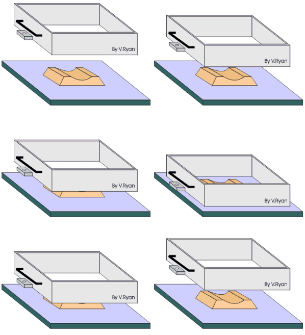
The diagrams to the left shows the pattern on a flat
board and a casting box called a ‘drag’ being placed over it. |
| |
|
|

|
Special casting sand will soon be packed around the
pattern but to ensure to can be removed easily from the sand, parting
powder is sprinkled over and around it. (parting powder is similar to
talcum powder). It stops the casting sand sticking to the pattern and
pulling away with it when the pattern is finally removed from the sand. |
|

|
Casting sand is then shaken through a sieve (called
riddled sand) so that only fine particles fall around the pattern. This is
called facing sand and it must be fine so that detail on the pattern shows
up on the final casting.
Different types of sand are available. The safest is called petro-bond. This
is a mixture of quality sand and oil. The cheapest is called green sand and
this is mixed with water. Green sand must be mixed carefully as if too much
water is added - when molten aluminium is poured into the mould an explosion
can result. |
FOUNDRY WORK (2)
V. Ryan © 2003 - 2009
|
|
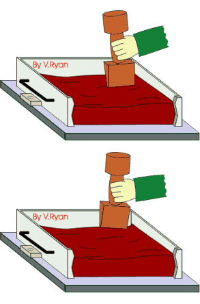
The drag is then packed with more casting sand. It is a
good idea to sieve all the sand being placed above the pattern and then
ram it down firmly using a ramming tool. The tool has two ends, one is
cylindrical and is used for general packing down of the sand. The other
end is quite pointed and this can be used for packing sand close up to the
pattern. |
|
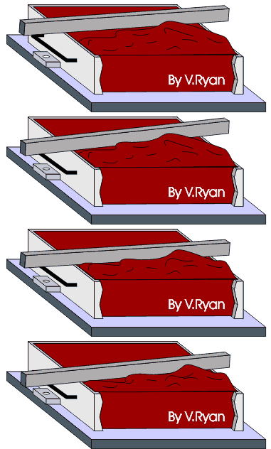
When the drag is packed fully it is levelled off
(called ‘strickled off’) using a straight steel bar. |
| |
|
|
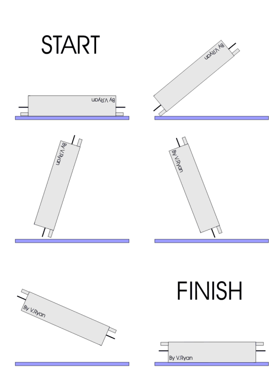
| The entire drag and its contents are then
turned over so that the base of the pattern can be seen. |
|
|
 |
| |
|
|
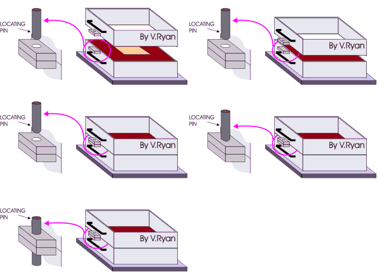
A top box called a ‘cope’ is then placed on top of the
drag and locating pins are put in position so that the casting boxes cannot
move sideways. |
| |
|
|
|
FOUNDRY WORK (3)
V. Ryan © 2003 - 2009
|
|
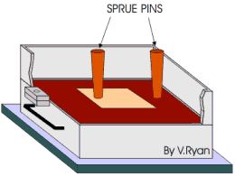
Sprue pins are positioned. One usually on the back of
the pattern and the other to the side. These will eventually provide an
entrance and exit for the molten aluminium when it is poured into the
sand.
The sand is packed/rammed into the cope in the same way as the drag.
Parting powder is first applied, followed by facing sand. The sprue pins
should be taller than the box and stand out from the sand when it is
levelled with a strickling bar. |
|
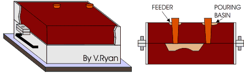
Small depressions are dug into the sand at the top of
the two sprue pins. These are useful when the aluminium is poured. The
depressions are called the pouring basin and feeder. |
| |
|
|
| |
|
|
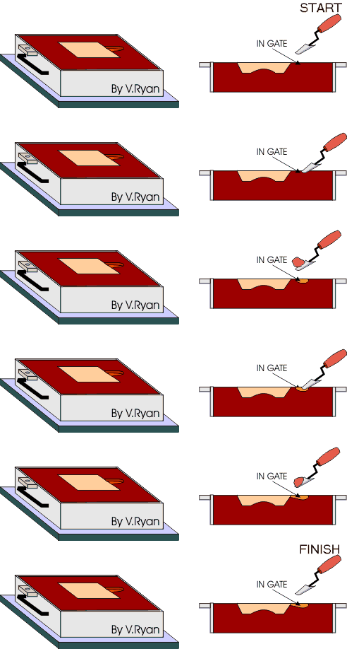
The top box (the cope) is then removed and if all is
well the cope with the sand inside should lift off the drag (bottom box)
without the sand falling out. A small ‘gate’ is cut below the position of
one of the sprue pins. This will help the molten aluminium flow into the
cavity left by the mould. Small tools are available or can easily be made
to dig a variety of shapes in the casting sand. They are similar to small
trowels. |
| |
|
|
|
|
|
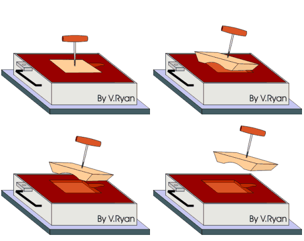
The pattern is removed using a ‘spike’. The end of the
spike can be threaded and so it can be screwed into the softwood pattern.
Before removing the pattern it is a good idea to gently tap the spike so
that it loosens the pattern from the sand. It can then be lifted away from
the casting box (drag). |
FOUNDRY WORK (4)
V. Ryan © 2003 - 2009
|
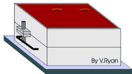
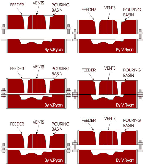
The cope (top casting box) is placed back on top of the
drag and the locating pins put in position. Before this is done vents can
be created using a thin piece of welding rod, pushing it through the sand
. This allows gases to escape once the aluminium is poured. |
| |
|
|
|
|
|
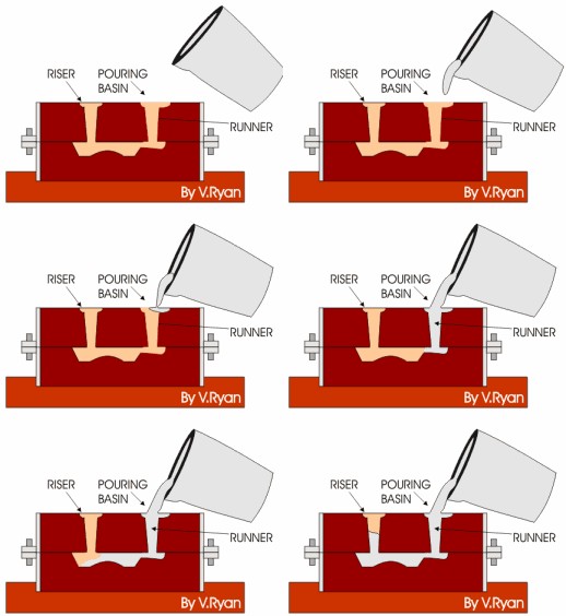
The aluminium is poured with great care. This is
discussed in detail on other information sheets. The aluminium is poured
down the hole left by the first sprue pin (now called the ‘runner’). As it
runs down the runner it flows through the ‘gate’ cut by the trowel, into the
cavity left by the pattern and up the riser (the hole left by the second
sprue pin).
The casting should be left for at least an hour before removal from the
sand. |
| |
|
|
|
|
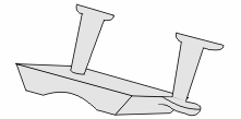
When removed from the sand, the runner and riser are cut
away and the casting is ready for machining. |
|
THE FURNACE
V. Ryan © 2003
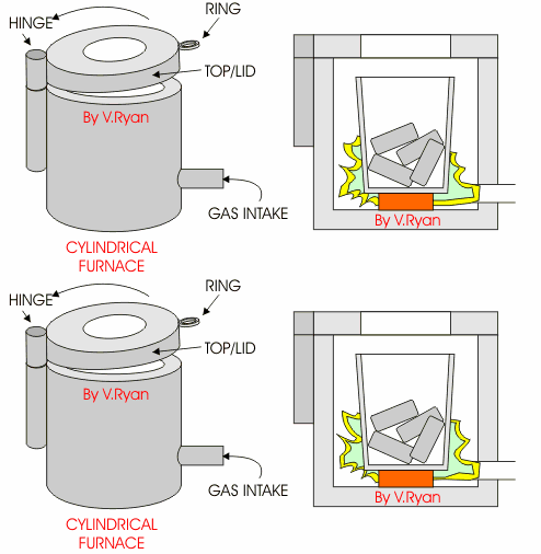
This is a typical cylindrical shaped furnace for the casting
of aluminium. The lid/top can be pulled back by placing a steel hook in the
‘ring’ and gently pulling the lid to the side. This allows the crucible to be
removed or ingots to be added.
The gas blows through the intake and ignites inside the furnace and swirls
around the crucible dispersing the heat.
Safety is very important as very high temperatures are reached. There are
potential dangers if safety equipment is not used or safety procedures not
followed.
SAFETY EQUIPMENT
V. Ryan © 2003
|
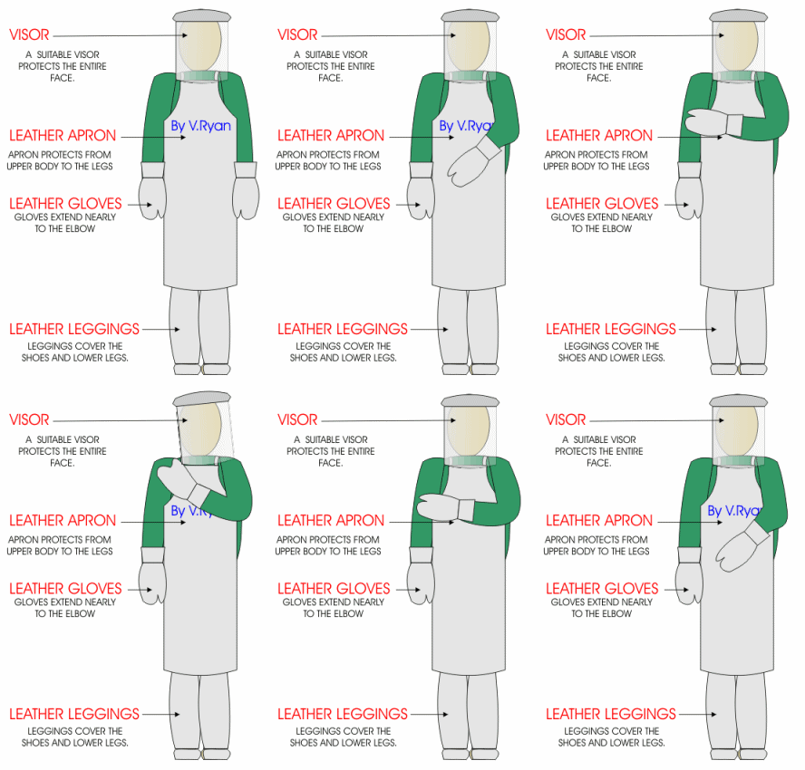
Appropriate safety must be worn when casting metals.
Aprons, gloves and leggings should be leather as this offers the most
protection is a spillage of molten aluminium occurs. Normal textile
material burns through very quickly and should not be used for the casting
process.
In addition, strong, leather shoes should be worn at all times in the
workshop as they offer the best protection for feet. In industry shoes
with steel toe caps are a basic requirement. |
|
|
|
| |
|
THE CASTING PROCEDURE (1)
V. Ryan © 2003 - 2009
|
PDF FILE - CLICK HERE
FOR PRINTABLE WORKSHEET |
| |
|
The procedure for preparing aluminium ingots for
casting must to be carried out carefully as safety is one of the key
concerns, whether in a school workshop or in industry. Outlined below are
the stages involved in heating and charging a crucible and then pouring
the molten aluminium. |
| |
|
|
|
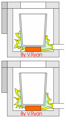
PREHEATING - The
crucible is first preheated. This removes any moisture from the furnace
and crucible. Usually the gas is turned half on in order to avoid rapid
heating. The aluminium ingots to be used are placed on top of the furnace
so that they warm up. |
| |
|
|

|
CHARGING WITH ALUMINIUM
- once the crucible and furnace have been preheated the lid/top is pulled
to one side with a steel hook. Aluminium ingots are then placed into the
crucible with steel tongs. All steel tools such as tongs are pre-warmed.
The gas pressure is turned up to full. |
|

|
ADDING FLUX - As the
aluminium begins to melt a small amount of ‘flux’ is sprinkled over the
aluminium. A spoon can be used to sprinkle the flux powder. The flux
prevents oxidisation (oxygen entering the molten aluminium). If oxygen
enters the molten aluminium, when it is poured into the mould the final
casting can have bubbles which can ruin the finish of the cast shape. |
|
|
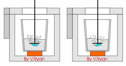
ADDING A DEGASSING TABLET
- When the aluminium has melted fully and is approximately 700 degrees
centigrade the gas is turned off and a degassing tablet is added. This
removes any impurities, in the form of gas. It is important that a good
extraction system is used to remove the fumes caused by the tablet.
PLEASE NOTE - it is
not vital to use flux or a degassing tablet. The degassing tablet causes a
lot of fumes which can be a problem in an enclosed workshop. |
THE CASTING PROCEDURE (2)
V. Ryan © 2003
|
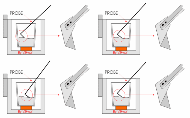
TEMPERATURE CONTROL
- Judging the temperature of the molten aluminium is sometimes difficult.
Using a pyrometer, the instrument used for testing temperature, allows
accurate measurement. The pyrometer is first warmed over the furnace to
evaporate any moisture and then it is placed into the molten metal The
temperature can be read on the meter, near the handle. |
|

|

|
|
When the temperature reaches 650 degrees it is ready
for pouring but first the ‘dross’ (waste that collects on the surface of
the aluminium) must be removed with a special tool. |
 |
|
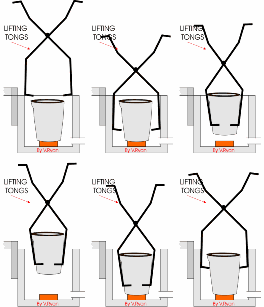
CRUCIBLE LIFTED OUT OF FURNACE - The sliding lid/top of the furnace is pulled back using a steel
hook. This allows special lifting tongs to be placed around the crucible
which can then be lifted up and away from the furnace. The crucible is set
to rest in a bed of sand which surrounds the furnace. The crucible should
never be allowed to rest directly on a the cold concrete floor as this could
cause an explosion.
This process should never be carried out by a pupil. Great care is needed as
the molten aluminium is at a very high temperature. |
| |
|
|
|

|
THE CASTING PROCEDURE (3)
V. Ryan © 2003
|
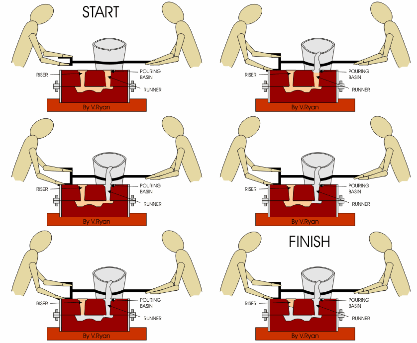
POURING THE ALUMINIUM
- The two man ladle is then lifted which raises the crucible from the
floor. The teacher must always control the pouring of the molten metal and
so holds the two handles. The second person (possibly a pupil) holds the
single handle allowing it to revolve when the ladle is turned for pouring
by the teacher. A third person stands behind the crucible and uses a steel
steady to prevent the crucible from falling out of the ladle.
The aluminium is poured into the runner and when the cavity is full is
rises up the riser. The flow of aluminium should be constant, if there is
even a short break in pouring the cast aluminium it may cool and the cast
may be imperfect.
SAFETY CLOTHING MUST BE WORN !! |
| |
|
|
|
|
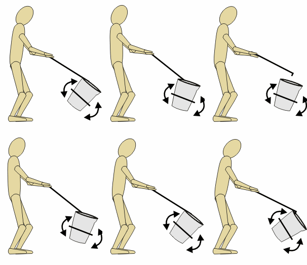
The third person stands behind the crucible and uses a
steel steady to prevent the crucible falling forward and out of the ladle. |
|
SMALL SCALE ALUMINIUM CASTING
PREPARING THE COPE (TOP BOX)
V. Ryan © 2008 - 2009
| Aluminium can be used as a material for small
scale casting. Aluminium looks similar to pewter but has a much higher
melting point (650 - 700 degrees centigrade). It also is stronger and more
resistant to ‘knocks’ and scratches. It is much cheaper than pewter but
must be heated for quite a long time on the brazing hearth before it
becomes molten. |
|
|

|
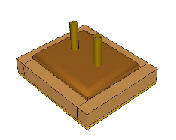
A base is prepared. This has two holes that will hold
the sprues in place whilst the casting sand is used to fill the box. The
sprues will eventually form the holes down which the molten aluminium will
be poured and rise during the casting operation.
Small casting boxes are used if small casts are to be manufactured. The
top casting box is called the ‘cope’ and the lower box is the ‘drag’. |
|
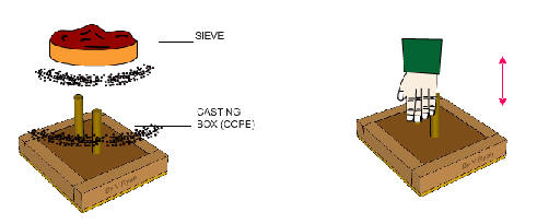
When the sprues, base and sides are in position,
casting sand (normally petrabond) is built up in the casting box (the
cope).
A small fine sieve is used to ensure lumps’ of petrabond are broken down
and that only fine sand is allowed to build up around the sprues. Hands
and fingers can be used to compress the sand. |
|
|
|
|
Sand is then built up around the sprues, above the
level of the box. This sand will eventually prevent excess molten
aluminium from spilling over the side of the casting box (the cope). |
|
|
|
A small trowel or even a spoon is used to ‘dig’ gates
around each sprue. The aluminium will be poured into the gate of one of
the holes made by the sprues, flowing down into the cavity and rising up
the other hole. |
 |
|

|
The sprues are carefully removed leaving the holes that
are now known as the ‘runner’ and ‘riser’.
The molten aluminium will be poured into the ‘runner’ and rise up the
‘riser’.
The COPE - the top casting box is complete. |
SMALL SCALE ALUMINIUM CASTING
PREPARING THE DRAG (BOTTOM BOX)
V. Ryan © 2008 - 2009
SMALL SCALE ALUMINIUM CASTING
HEATING AND POURING THE ALUMINIUM
V. Ryan © 2008 - 2009
|
The animation below shows pieces of aluminium cut to a
size suitable for heating in a ladle. Fire bricks have been arranged
around the bowl of the ladle so that the heat from the brazing torch flame
is reflected back onto the aluminium. As the temperature rises to 650
degrees centigrade the aluminium begins to become molten and quite quickly
forms a liquid. |
|
 |
|
The molten aluminium is carefully poured into the
mould. The casting boxes are set in sand in case any of the molten
aluminium runs down the sides. If this happens the molten aluminium will
simply stay on the surface of the sand and cool down. The casting boxes
should never be placed on a cold surface. If molten metal comes in contact
with a cold surface it will ‘splatter’ violently. Anyone close to the area
will be in serious danger. |
| |
|
|
|
When the aluminium has cooled down it can be removed
from the petrabond sand. Great care should be taken because it the
aluminium retains heat for sometime.
When completely cool the sprues can be removed with a hacksaw and
recycled. The casting can be cleaned up using files, emery cloth and a
polishing machine. |
|
Pewter is an ALLOY which means it is composed of more
than one metal. Most modern pewter is composed of 96 percent tin and 4
percent copper although there are many variations. It is a soft metal and
can be shaped easily by hand tools and machine tools. Due to its low melting
point (approximately 230 degrees centigrade) it is suitable for casting. It
is a bright material, which makes it popular for the manufacture of
‘silverware’ such as tankards, candlesticks and even jewellery. |
|
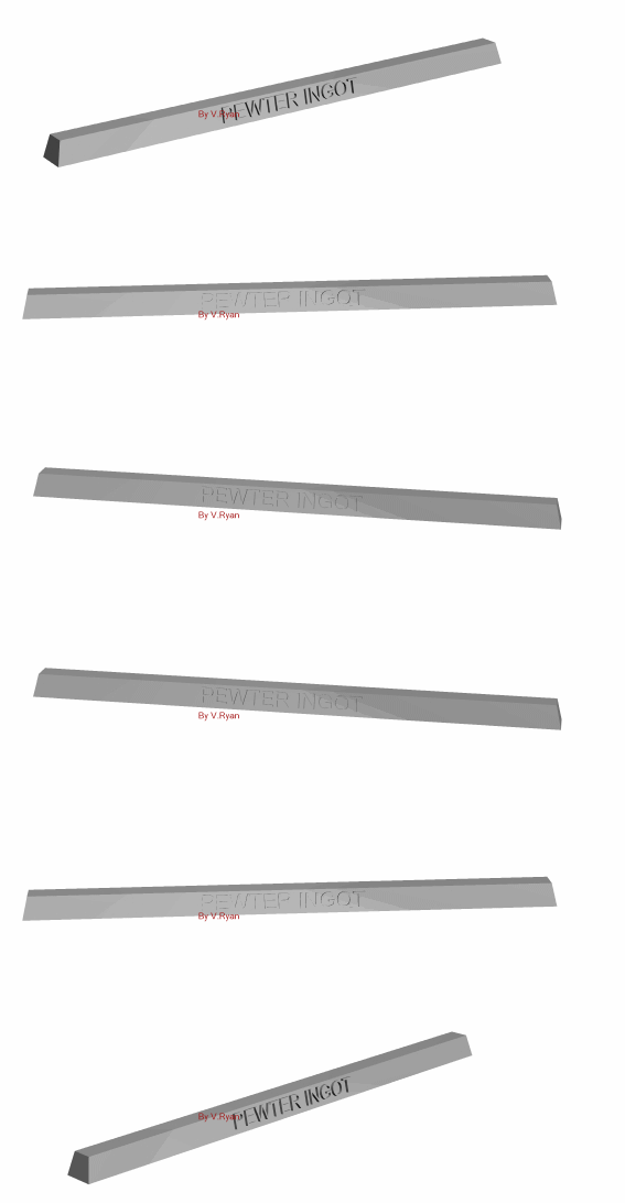
Pewter can be purchased as ingots and a typical ingot is
shown below. Because pewter is malleable (soft) it can be cut with a hacksaw
easily. When preparing to cast pewter small pieces of approximately 60mm in
length are cut. This size will fit comfortably in the ‘bowl’ of a casting
ladle, ready for casting. |
| |
|
 |
|
Before casting can take place a mould must be made.
Moulds can be made from a range of materials including MDF, steel, silica
sand or even oil based casting sands such as ‘petrabond’. In schools and
colleges, MDF is an ideal material and moulds made from this material can be
reused a small number of times. An example of a mould is seen below. It has
two parts and they are held together with wire or small cramps. |
| |
|
 |
The pattern/cavity can be cut in the MDF using hand tools or
for accurate results a CNC machine can be used. A natural material such as
Cuttlefish bone can also be used. Cuttlefish bone is a soft material and is the
shell of the cuttlefish usually found in the Indian Ocean. It can be craved into
detailed shapes and in this way a pattern can be cut into its surface and this
can be used as the mould.
PEWTER CASTING - 2
V. Ryan © 2006 - 2009
|
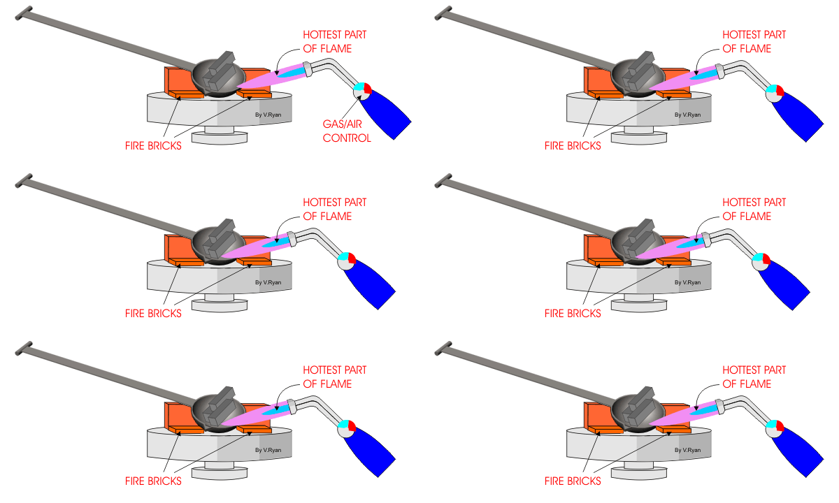
The diagram below shows pieces of the pewter ingot cut
to a size suitable for heating in a ladle. Fire bricks have been arranged
around the bowl of the ladle so that the heat from the brazing torch flame
is reflected back onto the ladle. As the temperature rises the pewter
begins to melt and quite quickly forms a molten liquid. |
| |
|
 |
| |
|
|
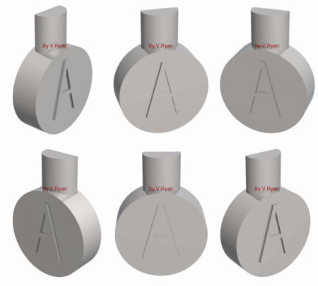
The molten pewter is then carefully poured into the
mould. The mould is set in sand in case any of the molten pewter runs down
the side of the mould. If this happens the molten pewter will simply stay
on the surface of the sand and cool down. The mould should never be placed
on a cold surface. If molten metal comes in contact with a cold surface it
will ‘splatter’ violently. Anyone close to the area will be in serious
danger. |
| |
|
 |
|
|
When the pewter has cooled the mould is split open and
the casting removed. The pewter casting will need some work with hand tools
and the ‘waste material will need removing. Pewter is extremely soft and
malleable making it easy to shape. |
PEWTER CASTING AND SAFETY
V. Ryan © 2006 - 2009
|
Pewter casting is potentially very dangerous because of
the high temperatures involved. Safety clothing similar to the type shown
below must be worn and it is essential that all possible safety
measures/precautions are taken. Pupils / students must be supervised
directly during any casting. |
|
| |
|
|
Appropriate safety must be worn when casting metals.
Aprons, gloves and leggings should be leather as this offers the most
protection if a spillage of molten pewter occurs. Normal textile material
burns through very quickly and should not be used for the casting process.
In addition, strong, leather shoes should be worn at all times in the
workshop as they offer the best protection for feet. In industry shoes
with steel toe caps are a basic requirement. |

|
MDF MOULDS AND PEWTER CASTING - SMALL SCALE CASTING - 1
V. Ryan © 2008 - 2009
|
MDF is ideal for use as a mould when casting pewter.
The melting point of pewter is low and does not burn or damage the MDF so
that it can be reused time and time again. |
|
 |
|
The sides are generally manufactured from 9mm MDF with
the mould being made from 4mm MDF. The shape of the mould can be cut using
a coping saw or a fretsaw. The mould is usually quite small so care is
needed when cutting and shaping. It can be smoothed with fine glass paper.
|
| |
|
|
|
1. Cut a small piece of 4mm thick MDF. |
|
|
2. Draw a simple shape on the MDF include the ‘sprue’.
The sprue is the top part of the mould, into which the molten pewter is
poured. |
|
|
3. Cut away the shape using either a fretsaw or a
coping saw. Smooth the rough edges with fine glass paper. The mould is now
ready. |
MDF MOULDS AND PEWTER CASTING - SMALL SCALE CASTING - 2
V. Ryan © 2008 - 2009
|
When the mould is finished it is placed between the two
supporting pieces of MDF and secured in a vice. A hot air gun is normally
used to strip old paint from wood. However, it is ideal for heating up
pewter and usually takes about two to three minutes before it is ready for
pouring. |
|
 |
|
|
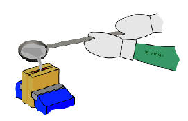
When the pewter is molten it is ready to pour into the
mould. Safety equipment should be worn when carrying out this procedure.
Leather gloves, a safety visor and leather apron are usually worn. |
|

|
When pouring is finished a small amount of pewter is
normally left above the sprue. This must be removed quickly by pushing a
piece of wood along the top. The excess pewter falls to the side and can
be recycled later.
The casting is allowed to cool and removed from between the supporting
pieces. |
|
|
|
If drilling is needed a hand vice is used to hold the
casting. This is a safe technique. The hand vice has two jaws that are
closed by turning a wing nut. (See below). |
| |
|
|
The pewter letter is finally cleaned / smoothed by
using of emery cloth. A small amount of oil is added and the letter is
moved forwards and backwards. Smoothing the surfaces can take a
considerable amount of time however, the finish is very good.
If a polished surface is required a polishing machine can be used. |
Casting Defects:
The defects in a casting may be due to pattern and moulding box equipment,
moulding sand, cores,gating system or molten metal. Some of the defects are:
1: Mould shift
It results in a mismatching of the top and the bottom parts of the casting ,
usually at the parting line.
2: Swell
It is an enlargement of the mould cavity by molten metal pressure resulting in
localized or general enlargement of the casting.
3: Fins and Flash
These are thin projections of the metal not intended as a part of casting.
These usually occurs at the parting line of the mould.
4:
SandWash
It usually occurs near the in the gates as rough lumps on the surface of a
casting.
5: Shrinkage
It is a crack or breakage in the casting on the surface of the work piece,
which results from un equal contraction of the metal during solidification.
6: Hot Tear
It is an internal or external ragged discontinuously in the metal casting
resulting just after the metal has solidified.
7: Sand Blow or Blow Hole
It is smooth depression on the outer surface of the casting work piece.
8: Honeycombing or Slag holes
These are smooth depression on the upper surface of the casting. They usually
occur near the ingates.
9: Scabs
These are patches of sand on the upper surface of the casting component.
10: Cold Shut and Misruns
These happens when the mould cavity is not completely filled by the molten and
insufficient material or metal.
11: Run-outs and Bust-outs
These permit drainage of the metal from the cavity and result in incomplete
casting.
“Pattern”- making, allowances and its
types:
Pattern:
A pattern may be defined as a model of
desired casting which when moulded in sand forms an impression called mould.
The mould when filled with the molten metal forms casting after
solidification of the poured metal. The quality and accuracy of casting
depends upon the pattern making. The pattern may be made of wood, metal(cast
iron, brass, aluminium and alloy steel.), plaster, plastics and wax.
Pattern Allowances:
A pattern is always made larger than the
required size of the casting considering the various allowances. These are
the allowances which are usually provided in a pattern.
1: shrinkage or contraction allowance:
The various metals used for casting contract
after solidification in the mould. Since the contraction is different for
different materials, therefore it will also differ with the form or type of
metal.
2: Draft allowance
It is a taper which is given to all the
vertical walls of the pattern for easy and clean withdraw of the pattern
from the sand without damaging the mould cavity. It may be expressed in
millimeters on a side or in degrees. The amount of taper varies with the
type of patterns. The wooden patterns require more taper than metal patterns
because of the greater frictional resistance of the wooden surfaces.
3: Finish or machining allowance
The allowance is provided on the pattern if
the casting is to be machined. This allowance is given in addition to
shrinkage allowance. The amount of this allowance varies from 1.6 to 12.5 mm
which depends upon the type of the casting metal, size and the shape of the
casting. The ferrous metals require more machining allowance than non
ferrous metals.
4: Distortion or camber allowance
This allowance is provided on patterns used
for casting of such design in which the contraction is not uniform
throughout.
5: Rapping or shaking allowance
This allowance is provided in the pattern to
compensate for the rapping of mould because the pattern is to be rapped
before removing it from the mould.
Types of Patterns:
The common types of patterns are as follows:
<!--[if !supportLists]-->1. <!--[endif]-->solid or single
piece patterns
<!--[if !supportLists]-->2. <!--[endif]-->split or
two/multiple piece patterns
<!--[if !supportLists]-->3. <!--[endif]-->match plate
pattern
<!--[if !supportLists]-->4. <!--[endif]-->cope and drag
pattern
<!--[if !supportLists]-->5. <!--[endif]-->loose piece
pattern
<!--[if !supportLists]-->6. <!--[endif]-->gated patterns
<!--[if !supportLists]-->7. <!--[endif]-->sweep pattern
<!--[if !supportLists]-->8. <!--[endif]-->skeleton pattern
<!--[if !supportLists]-->9. <!--[endif]-->shell pattern
<!--[if !supportLists]-->10. <!--[endif]-->segmental pattern
<!--[if !supportLists]-->11. <!--[endif]-->follow board
pattern
<!--[if !supportLists]-->12. <!--[endif]-->lagged up pattern
<!--[if !supportLists]-->13. <!--[endif]-->left and right
hand pattern
Special Casting Processes:
The sand moulds may be used for casting
ferrous and non-ferrous metals, but these moulds can be used only once,
because the mould is destroyed after the metal has solidified. This will
increase the cost of production. The sand moulds also, can not maintain the
tolerance and smooth surface finish. In order to meet these requirements,
following casting method may be use:
1: Permanent Mould Casting
A casting made by pouring molten metal by
gravity into a mould made of some metallic alloy or other material of
permanence is known as permanent mould casting.
2: Slush Casting
The slush casting is a special application
involving the used of permanent mould. It is used for casting low melting
temperature alloys. This method is only adopted for ornaments and toys of
non-ferrous alloys.
3: Die Casting
The die casting (also known as pressure die
casting) may be defined as that casting which uses the permanent
mould(called die) and the molten metal is introduced into it by means of
pressure, following are two type of die casting machines commonly used for
die casting:
<!--[if !supportLists]-->(a) <!--[endif]-->Hot
chamber die casting machine
In a hot chamber die casting machine, the
melting pot is an integral part of the machine. The molten metal is forced
in the die cavity at pressure from 7 to 14 MPa. The pressure may be obtained
by compressed air or by hydraulically operated plunger. The hot chamber die
casting machine is use for casting zinc, tin, lead and other low casting
melting alloys.
<!--[if !supportLists]-->(b) <!--[endif]-->Cold
chamber die casting machine
In a cold chamber die casting machine , the
melting pot is usually separate from the machine and the molten metal is not
transferred to injection mechanism by ladle. The pressure on the casting
metal may vary from 21 to 210 MPa and in same cases may reach 700 MPa. This
process is used for casting aluminum, magnesium, copper, brass alloys and
other high melting alloys.
4: Centrifugal Casting
A casting process in which the molten metal
is poured and allowed to solidify while the mould is revolving, is called
centrifugal process. The casting produced under this centrifugal force is
called centrifugal casting. This process is especially designed for casting
of symmetrical shape. The ferrous and the non-ferrous metals can be obtained
by this process. The casting produced by this process have dense and fine
grained structure.
5: Investment Casting
It is also known as lost wax process or
precision casting. The casting produced by this method are within very close
tolerance(±0.05mm).
6: Shell Moulding Process
The shell moulding process is also called
croning process. The shell cast part can be produced with dimensional
tolerance of ±02 mm.
Moulding sand properties and its
classification:
The moulding is a process of making a cavity
or mould out of sand by means of a pattern. The molten metal is poured into
the moulds to produce casting.
Properties of moulding sand
1: porosity or permeability
It is the property of sand which permits the
steam and other gases to pass through the sand mould. The porosity of sand
depends upon its grain size, grain shape, moisture and clay components are
the moulding sand. If the sand is too fine, the porosity will be low.
2: Plasticity
It is that property of sand due to which it
flows to all portions of the moulding box or flask. The sand must have
sufficient plasticity to produce a good mould.
3: Adhesiveness
It is that properties of sand due to it
adheres or cling to the sides of the moulding box.
4: Cohesiveness
It is the property of sand due to which the
sand grains stick together during ramming. It is defined as the strength of
the moulding sand.
5: Refractoriness
The property which enables it to resist high
temperature of the molten metal without breaking down o r fusing.
Classification of Moulding sand
according to their use:
1: Green sand
The sand in its natural or moist state is
called green sand. It is also called tempered sand. It is a mixture of sand
with 20 to 30 percent clay, having total amount of water from 6 to 10
percent. The mould prepared with this sand is called green sand mould, which
is used for small size casting of ferrous and non-ferrous metals.
2: Dry Sand
The green sand moulds when baked or dried
before pouring the molten metal are called dry sand moulds. The sand of this
condition is called dry sand. The dry sand moulds have greater strength,
rigidity and thermal stability. These moulds used for large and heavy
casting.
3: Loam Sand
A mixture of 50 percent sand grains and 50
percent clay is called loam sand. It is used for loam moulds of large grey
iron casting.
4: Facing Sand
A sand which is used before pouring the
molten metal, on the surface is called facing sand. It is specially prepared
sand from silica sand and clay.
5: Backing or Floor Sand
A sand used to back up the facing sand and
not used next to the pattern is called backing sand. The sand which have
been repeatedly used may be employed for this purpose. It is also known as
black sand due to its colour.
6: System Sand
A sand employed in mechanical sand
preparation and handling system is called system sand. This sand has high
strength, permeability and refractoriness.
7: Parting Sand
A sand employed on the faces of the pattern
before the moulding is called parting sand. The parting sand consists of
dried silica sand, sea sand or burnt sand.
8: Core Sand
The cores are defined as sand bodies used to
form the hollow portions or cavities of desired shape and size in the
casting. Thus the sand used for making these cores is called core sand. It
is sometimes called oil sand. It is the silica sand mixed with linseed oil
or any other oil as binder.
Casting Defects:
The defects in a casting may be due to
pattern and moulding box equipment, moulding sand, cores,gating system or
molten metal. Some of the defects are:
1: Mould shift
It results in a mismatching of the top and
the bottom parts of the casting , usually at the parting line.
2: Swell
It is an enlargement of the mould cavity by
molten metal pressure resulting in localized or general enlargement of the
casting.
3: Fins and Flash
These are thin projections of the metal not
intended as a part of casting. These usually occurs at the parting line of
the mould.
4:
SandWash
It usually occurs near the in the gates as
rough lumps on the surface of a casting.
5: Shrinkage
It is a crack or breakage in the casting on
the surface of the work piece, which results from un equal contraction of
the metal during solidification.
6: Hot Tear
It is an internal or external ragged
discontinuously in the metal casting resulting just after the metal has
solidified.
7: Sand Blow or Blow Hole
It is smooth depression on the outer surface
of the casting work piece.
8: Honeycombing or Slag holes
These are smooth depression on the upper
surface of the casting. They usually occur near the ingates.
9: Scabs
These are patches of sand on the upper
surface of the casting component.
10: Cold Shut and Misruns
These happens when the mould cavity is not
completely filled by the molten and insufficient material or metal.
11: Run-outs and Bust-outs
These permit drainage of the metal from the
cavity and result in incomplete casting.
Moulding sand properties and its classification:
The moulding is a process of making a cavity or mould out of sand by means of
a pattern. The molten metal is poured into the moulds to produce casting.
Properties of moulding sand
1: porosity or permeability
It is the property of sand which permits the steam and other gases to pass
through the sand mould. The porosity of sand depends upon its grain size,
grain shape, moisture and clay components are the moulding sand. If the sand
is too fine, the porosity will be low.
2: Plasticity
It is that property of sand due to which it flows to all portions of the
moulding box or flask. The sand must have sufficient plasticity to produce a
good mould.
3: Adhesiveness
It is that properties of sand due to it adheres or cling to the sides of the
moulding box.
4: Cohesiveness
It is the property of sand due to which the sand grains stick together during
ramming. It is defined as the strength of the moulding sand.
5: Refractoriness
The property which enables it to resist high temperature of the molten metal
without breaking down o r fusing.
Classification of Moulding sand according to their use:
1: Green sand
The sand in its natural or moist state is called green sand. It is also called
tempered sand. It is a mixture of sand with 20 to 30 percent clay, having
total amount of water from 6 to 10 percent. The mould prepared with this sand
is called green sand mould, which is used for small size casting of ferrous
and non-ferrous metals.
2: Dry Sand
The green sand moulds when baked or dried before pouring the molten metal are
called dry sand moulds. The sand of this condition is called dry sand. The dry
sand moulds have greater strength, rigidity and thermal stability. These
moulds used for large and heavy casting.
3: Loam Sand
A mixture of 50 percent sand grains and 50 percent clay is called loam sand.
It is used for loam moulds of large grey iron casting.
4: Facing Sand
A sand which is used before pouring the molten metal, on the surface is called
facing sand. It is specially prepared sand from silica sand and clay.
5: Backing or Floor Sand
A sand used to back up the facing sand and not used next to the pattern is
called backing sand. The sand which have been repeatedly used may be employed
for this purpose. It is also known as black sand due to its colour.
6: System Sand
A sand employed in mechanical sand preparation and handling system is called
system sand. This sand has high strength, permeability and refractoriness.
7: Parting Sand
A sand employed on the faces of the pattern before the moulding is called
parting sand. The parting sand consists of dried silica sand, sea sand or
burnt sand.
8: Core Sand
The cores are defined as sand bodies used to form the hollow portions or
cavities of desired shape and size in the casting. Thus the sand used for
making these cores is called core sand. It is sometimes called oil sand. It is
the silica sand mixed with linseed oil or any other oil as binder.
“Pattern”- making, allowances and its types:
Pattern:
A pattern may be defined as a model of desired casting which when moulded in
sand forms an impression called mould. The mould when filled with the molten
metal forms casting after solidification of the poured metal. The quality and
accuracy of casting depends upon the pattern making. The pattern may be made
of wood, metal(cast iron, brass, aluminium and alloy steel.), plaster,
plastics and wax.
Pattern Allowances:
A pattern is always made larger than the required size of the casting
considering the various allowances. These are the allowances which are usually
provided in a pattern.
1: shrinkage or contraction allowance:
The various metals used for casting contract after solidification in the
mould. Since the contraction is different for different materials, therefore
it will also differ with the form or type of metal.
2: Draft allowance
It is a taper which is given to all the vertical walls of the pattern for easy
and clean withdraw of the pattern from the sand without damaging the mould
cavity. It may be expressed in millimeters on a side or in degrees. The amount
of taper varies with the type of patterns. The wooden patterns require more
taper than metal patterns because of the greater frictional resistance of the
wooden surfaces.
3: Finish or machining allowance
The allowance is provided on the pattern if the casting is to be machined.
This allowance is given in addition to shrinkage allowance. The amount of this
allowance varies from 1.6 to 12.5 mm which depends upon the type of the
casting metal, size and the shape of the casting. The ferrous metals require
more machining allowance than non ferrous metals.
4: Distortion or camber allowance
This allowance is provided on patterns used for casting of such design in
which the contraction is not uniform throughout.
5: Rapping or shaking allowance
This allowance is provided in the pattern to compensate for the rapping of
mould because the pattern is to be rapped before removing it from the mould.
Types of Patterns:
The common types of patterns are as follows:
<!--[if !supportLists]-->1. <!--[endif]-->solid
or single piece patterns
<!--[if !supportLists]-->2. <!--[endif]-->split
or two/multiple piece patterns
<!--[if !supportLists]-->3. <!--[endif]-->match
plate pattern
<!--[if !supportLists]-->4. <!--[endif]-->cope
and drag pattern
<!--[if !supportLists]-->5. <!--[endif]-->loose
piece pattern
<!--[if !supportLists]-->6. <!--[endif]-->gated
patterns
<!--[if !supportLists]-->7. <!--[endif]-->sweep
pattern
<!--[if !supportLists]-->8. <!--[endif]-->skeleton
pattern
<!--[if !supportLists]-->9. <!--[endif]-->shell
pattern
<!--[if !supportLists]-->10. <!--[endif]-->segmental
pattern
<!--[if !supportLists]-->11. <!--[endif]-->follow
board pattern
<!--[if !supportLists]-->12. <!--[endif]-->lagged
up pattern
<!--[if !supportLists]-->13. <!--[endif]-->left
and right hand pattern
Sand Casting Processes
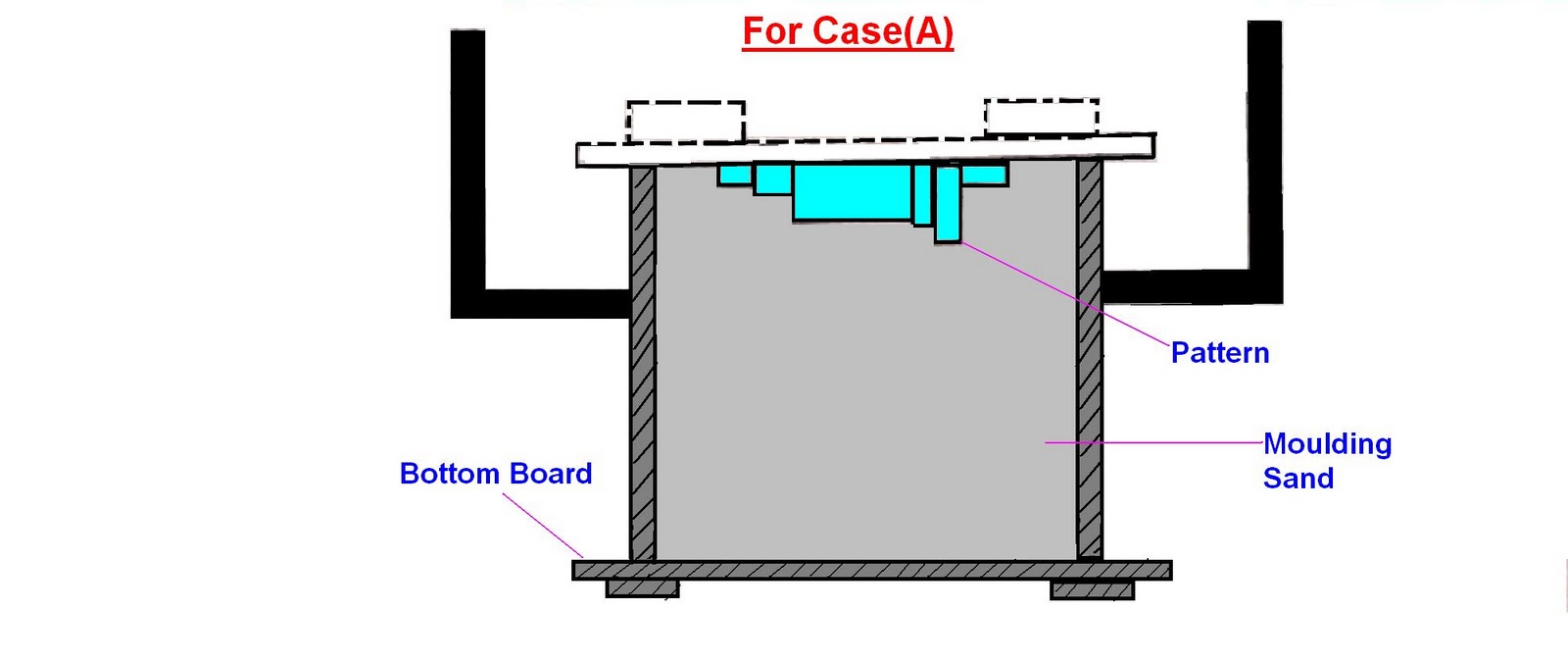
For Case(A):
Bottom board is placed either boundary moulding from or on the floor making
the surface even. The drag moulding flask is kept upside down on the bottom
board. Dry facing sand is sprinkled over the board. Rest of the drag flask is
completely filled with back up sand and uniform the rammed to compact the
sand. The remaining of sand should be done properly. So as to compact it to
hard , which makes the escape of gases difficult not to lose.
So that mould could not have enough strength . After the ramming is over , the
excess of sand in the flask is completely scraped using a flat bar to the
level of the flask edges. Now with a vent wire which is a wire of 1-2mm
diameter with a pointed end, vent holes are made in the drag to he full depth
flask as well as to the pattern to facilitate the removal of gases during
casting solidification. This complete the preparation of the drag.
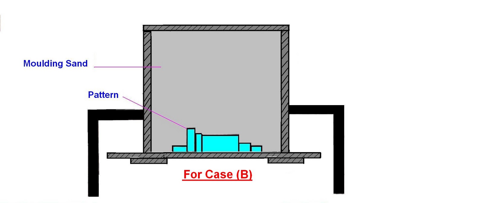
For case B:
We finished the drag flask is now rolled over to the bottom bolt exposing
the pattern and cope of the pattern is placed over the dragged pattern.
For case C:
The cope flask on the top of the drag is rotated aligning again with the help
of the pins. A screw pin for making the screw passage. The sand is thoroughly
rammed and excess sand scrap and vent holes are made over all in the cope as
in the drag. The screw pin and the riser pin are carefully with drawn from
flask the mould is now ready.
Shell moulding ;
It is a process in which the sand is mixed with a thermo setting resin is
allowed to come into contact a heated metallic pattern plate ‘so that a them
and strong shell of mould is formed around the pattern’ then she is removed
the pattern and the cope and drag are remove together and kept in a flask with
the necessary back up material and the molten metal is pored into the mould.
Generally dry and fin sand which is completely free of the clay is used for
preparing the shell mould in are the phenol formaldehyde rising combined with
sand they hare very high strength and resistance through heat.
Steps Involve;
Step 1;
A
metal pattern having the profile of the
required
casting is heated to 180°-260°c in an own maintained at 300°-400°c pattern
after being heated is taken out of the own and sprayed with a solution of a
lubricating agent containing silicon. It is necessary to prevent the shell
from sticking to the metal pattern.
Step 2:
Metal pattern(made up of iron or steel )is then turned faced down and clamped
over the open end of the dump box.
Step 3:
the dump box is inverted so that dry sand raisin mixture falls on the face of
hot metal pattern . the raisin the raisin softens and fuses to form a soft and
uniform sand mixture in contact with the pattern gets heat up .the
rasinsoftens and fuses to form a soft and uniform shell of about 6mm thickness
on the surface of pattern.
Step 4;
As the dump box is turned to its original position. Excess sand resin mixture
falls beak into the dump box leaving a shell adhering closely to the pattern
Step 5;
The shell is then stripped from the pattern plate with the help of ejector
pins which are an integral part of the metal pattern
Step 6;
After the shells so obtained have cooled. Two meeting shell are securely
fastened together to from a complete mould.
Special Casting Processes:
The sand moulds may be used for casting ferrous and non-ferrous metals, but
these moulds can be used only once, because the mould is destroyed after the
metal has solidified. This will increase the cost of production. The sand
moulds also, can not maintain the tolerance and smooth surface finish. In
order to meet these requirements, following casting method may be use:
1: Permanent Mould Casting
A casting made by pouring molten metal by gravity into a mould made of some
metallic alloy or other material of permanence is known as permanent mould
casting.
2: Slush Casting
The slush casting is a special application involving the used of permanent
mould. It is used for casting low melting temperature alloys. This method is
only adopted for ornaments and toys of non-ferrous alloys.
3: Die Casting
The die casting (also known as pressure die casting) may be defined as that
casting which uses the permanent mould(called die) and the molten metal is
introduced into it by means of pressure, following are two type of die casting
machines commonly used for die casting:
<!--[if !supportLists]-->(a) <!--[endif]-->Hot
chamber die casting machine
In a hot chamber die casting machine, the melting pot is an integral part of
the machine. The molten metal is forced in the die cavity at pressure from 7
to 14 MPa. The pressure may be obtained by compressed air or by hydraulically
operated plunger. The hot chamber die casting machine is use for casting zinc,
tin, lead and other low casting melting alloys.
<!--[if !supportLists]-->(b) <!--[endif]-->Cold
chamber die casting machine
In a cold chamber die casting machine , the melting pot is usually separate
from the machine and the molten metal is not transferred to injection
mechanism by ladle. The pressure on the casting metal may vary from 21 to 210
MPa and in same cases may reach 700 MPa. This process is used for casting
aluminum, magnesium, copper, brass alloys and other high melting alloys.
4: Centrifugal Casting
A casting process in which the molten metal is poured and allowed to solidify
while the mould is revolving, is called centrifugal process. The casting
produced under this centrifugal force is called centrifugal casting. This
process is especially designed for casting of symmetrical shape. The ferrous
and the non-ferrous metals can be obtained by this process. The casting
produced by this process have dense and fine grained structure.
5: Investment Casting
It is also known as lost wax process or precision casting. The casting
produced by this method are within very close tolerance(±0.05mm).
6: Shell Moulding Process
The shell moulding process is also called croning process. The shell cast part
can be produced with dimensional tolerance of ±02 mm.