Methods of
Cutting operation:
1: Orthogonal Cutting Process:
Orthogonal cutting occurs when the major cutting edge of the tool is presented
to the work piece perpendicular to the direction of the feed motion.
Orthogonal cutting is shown in figure:
2: Oblique Cutting Process:
Oblique cutting occurs when the major edge of the cutting tool is presented to
the work piece at an angle which is not perpendicular to the direction of the
feed motion, its diagram show that chips removal are the continuous type.
Principle Elements of Metal Machining:
1: Cutting Speed:
The cutting speed can be defined as the relative surface speed between the
tool and the job. It is a relative term since either the tool or the job or
both may be moving during cutting. It is expressed in m/min.
2: Feed:
It may be defined as the relatively small the cutting tool relative to the
work piece in a direction which is usually perpendicular to the cutting speed
direction. It is expressed in mm/rev or mm/stroke.
It is more complex element as compare to the cutting speed. It is expressed
differently for various operations.
3:Depth of cut:
The depth of cut is the thickness of the layer of the metal remove in one cut
or pass measured in a direction perpendicular to the machine surface. The
depth of cut is always perpendicular to the direction feed motion.
Sheet metal Cutting Operations:
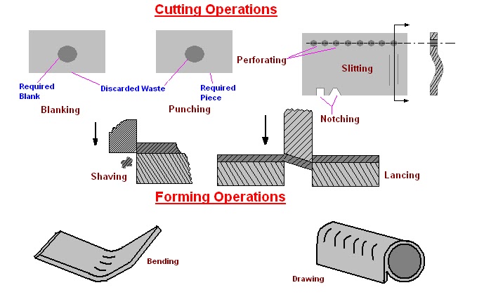
1: Blanking:
Blanking is the operation of cutting a flat shape from sheet metal. The
product punched out is called the “blank” and the required product of the
operation the hole and the metal left behind is discarded as waste.
2: Punching or Piercing:
It is a cutting operation by which various shaped holes are made in sheet
metal. Punching is similar to blanking except that in punching, the hole is
the desired product. The material punched out from the hole being waste.
3: Notching:
This is cutting operation by which metal pieces are cut from the edge of the
sheet , strip or blank.
4: Perforating:
This is a process by which multiple holes are very small and close together
are cut in a flat sheet metal.
5: Trimming:
This operation consists of cutting unwanted excess of material from the
periphery of a previously formed component.
6: Shaving:
The edge of a blanked part are generally rough, uneven and un square. Accurate
dimensions of the part are obtained by removing a thin strip of metal along
the edges.
7: Slitting:
It refers to the operation of making incomplete holes in a work piece.
8: Lancing:
This is a cutting operation in which a hole is partially cut and then one side
is bent down to form a sort of tab. Since no metal is actually removed and
there will be no scrap.
9: Nibbling:
The nibbling operation , which is used for only small quantities of
components, is designed for cutting out flat parts from sheet metal. The flat
parts from simple to complex contours. This operation is generally substituted
for blanking. The part is usually moved and guided by hand as the continuously
operating punch cutting away at the edge of the desired contour.
Forming Operations:
1: Bending:
In this operation; the material in the form of flat sheet or strip is
uniformly strained around a linear axis which lies in the neutral plane and
perpendicular it’s the length wise direction of the sheet or metal.
2: Drawing:
This is a process of forming a flat work piece into a hollow shape by means of
a punch which cause the blank into a die cavity.
3: Squeezing:
Under the operation, the metal is caused to flow to all portions of a die
cavity under the action of compressive forces.
Types of chips
The three common types of chip from a single point tool are.
1;:Discontinuous or segmental chip:
Discontinuous chips is formed by a series of rupture occurring approximately
perpendicular to the tool place face’ each chip element passing off along the
tool face the chip element’ in the form of small segment may adhere loosely to
each other and becomes slightly longer.
Since the chips break up into small segments the friction between the tool and
the chips reduces’ resulting in better surface finish. These chips are
convenient to collect’ handle and dispose off. Discontinuous chips tends to be
formed when one or more or the following conditions exist:
<!--[if !supportLists]-->1. <!--[endif]-->Brittle
material , such as cast iron and bronze.
<!--[if !supportLists]-->2. <!--[endif]-->large
chip thickness
<!--[if !supportLists]-->3. <!--[endif]-->low
cutting speed
<!--[if !supportLists]-->4. <!--[endif]-->small
rack angle
Discontinuous chips are also produced when cutting more ductile material with
the use of a cutting fluid.
2: Continuous Chips:
Continuous chips are formed by the continuous plastic deformation of metal
without fracture in front of the cutting edge of the tool and is formed by the
smooth flow of the chip up the tool face. Mild steel and copper are considered
to be most desirable materials for obtaining continuous chips. The chips
obtained have same thickness throughout. This type of chip is the most
desirable. Since it is stable cutting, resulting in generally good surface
finish. On the other hand these chips are difficult to handle and dispose off.
Continuous chips tend to be formed when the following condition exist:
<!--[if !supportLists]-->1. <!--[endif]-->ductile
material
<!--[if !supportLists]-->2. <!--[endif]-->high
cutting speed
<!--[if !supportLists]-->3. <!--[endif]-->small
chip thickness
<!--[if !supportLists]-->4. <!--[endif]-->large
rack angle
<!--[if !supportLists]-->5. <!--[endif]-->minimum
friction of chip on tool face by :
<!--[if !supportLists]-->· <!--[endif]-->polished
tool face
<!--[if !supportLists]-->· <!--[endif]-->use
of efficient cutting lubricants.
<!--[if !supportLists]-->· <!--[endif]-->Use
of tool material with low-coefficient of friction.
3: Continuous Chip with Built up Edge:
This type of chip is very similar to the continuous chip. With the difference
that it has a built up edge adjacent to tool face and also it is not so
smooth. It is obtained by machining on ductile material, in this condition of
high local temperature and extreme pressure in the cutting and high friction
in the tool chip interference, may cause the work material to adhere or weld
to the cutting edge of the tool. Successive layers of work material are then
added to the built up edge. When this edge becomes larger and unstable , it
breaks up and part of it is carried up the face of the tool along with the
chip while the remaining is left over the surface being machined, which
contributes to the roughness of the surface. The built up edge changes its
size during the cutting operation. It first increases , then decreases, then
again increases etc.