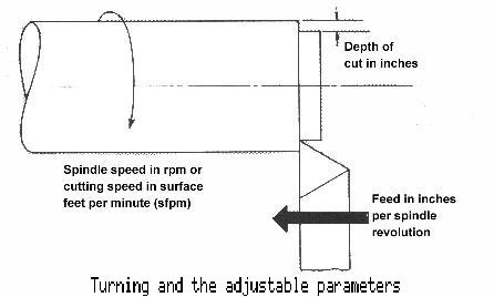
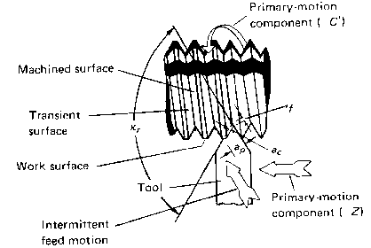
Turning is the machining operation that produces cylindrical parts. In its basic form, it can be defined as the machining of an external surface:
Taper turning is practically the same, except that the cutter path is at an angle to the work axis. Similarly, in contour turning, the distance of the cutter from the work axis is varied to produce the desired shape.
Even though a single-point tool is specified, this does not exclude multiple-tool setups, which are often employed in turning. In such setups, each tool operates independently as a single-point cutter.
View a typical turning operation. This movie is from the MIT-NMIS Machine Shop Tutorial.
The three primary factors in any basic turning operation are speed, feed, and depth of cut. Other factors such as kind of material and type of tool have a large influence, of course, but these three are the ones the operator can change by adjusting the controls, right at the machine.
Speed, always refers to the spindle and the workpiece. When it is stated in revolutions per minute(rpm) it tells their rotating speed. But the important figure for a particular turning operation is the surface speed, or the speed at which the workpeece material is moving past the cutting tool. It is simply the product of the rotating speed times the circumference (in feet) of the workpiece before the cut is started. It is expressed in surface feet per minute (sfpm), and it refers only to the workpiece. Every different diameter on a workpiece will have a different cutting speed, even though the rotating speed remains the same.
Feed, always refers to the cutting tool, and it is the rate at which the tool advances along its cutting path. On most power-fed lathes, the feed rate is directly related to the spindle speed and is expressed in inches (of tool advance) per revolution ( of the spindle), or ipr. The figure, by the way, is usually much less than an inch and is shown as decimal amount.
Depth of Cut, is practically self explanatory. It is the thickness of the layer being removed from the workpiece or the distance from the uncut surface of the work to the cut surface, expressed in inches. It is important to note, though, that the diameter of the workpiece is reduced by two times the depth of cut because this layer is being removed from both sides of the work.
The lathe, of course, is the basic turning machine. Apart from turning, several other operations can also be performed on a lathe.
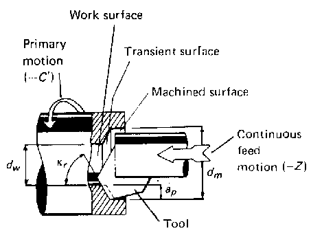
Boring. Boring always involves the enlarging of an existing
hole, which may have been made by a drill or may be the result of a core in a
casting. An equally important, and concurrent, purpose of boring may be to make
the hole concentric with the axis of rotation of the workpiece and thus correct
any eccentricity that may have resulted from the drill's having drifted off the
center line. Concentricity is an important attribute of bored holes. When boring
is done in a lathe, the work usually is held in a chuck or on a face plate.
Holes may be bored straight, tapered, or to irregular contours. Boring is
essentially internal turning while feeding the tool parallel to the rotation
axis of the workpiece.
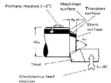
Facing. Facing is the producing of a flat surface as the result
of a tool's being fed across the end of the rotating workpiece. Unless the work
is held on a mandrel, if both ends of the work are to be faced, it must be
turned end for end after the first end is completed and the facing operation
repeated. The cutting speed should be determined from the largest diameter of
the surface to be faced. Facing may be done either from the outside inward or
from the center outward. In either case, the point of the tool must be set
exactly at the height of the center of rotation. because the cutting force tends
to push the tool away from the work, it is usually desirable to clamp the
carriage to the lathe bed during each facing cut to prevent it from moving
slightly and thus producing a surface that is not flat. In the facing of casting
or other materials that have a hard surface, the depth of the first cut should
be sufficient to penetrate the hard material to avoid excessive tool wear.
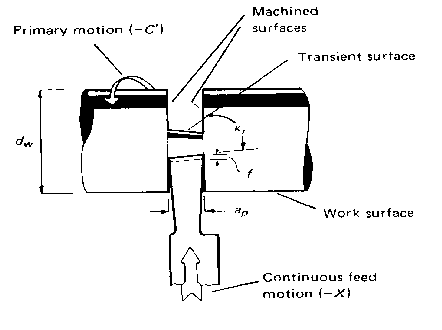
Parting. Parting is the operation by which one section of a
workpiece is severed from the remainder by means of a cutoff tool. Because
cutting tools are quite thin and must have considerable overhang, this process
is less accurate and more difficult. The tool should be set exactly at the
height of the axis of rotation, be kept sharp, have proper clearance angles, and
be fed into the workpiece at a proper and uniform feed rate.
Threading. Lathe provided the first method for cutting threads by machines. Although most threads are now produced by other methods, lathes still provide the most versatile and fundamentally simple method. Consequently, they often are used for cutting threads on special workpieces where the configuration or nonstandard size does not permit them to be made by less costly methods. There are two basic requirements for thread cutting. An accurately shaped and properly mounted tool is needed because thread cutting is a form-cutting operation. The resulting thread profile is determined by the shape of the tool and its position relative to the workpiece. The second by requirement is that the tool must move longitudinally in a specific relationship to the rotation of the workpiece, because this determines the lead of the thread. This requirement is met through the use of the lead screw and the split unit, which provide positive motion of the carriage relative to the rotation of the spindle.
Tool Geometry. For cutting tools, geometry depends mainly on
the properties of the tool material and the work material. The standard
terminology is shown in the following figure. For single point tools, the most
important angles are the rake angles and the end and side relief angles.
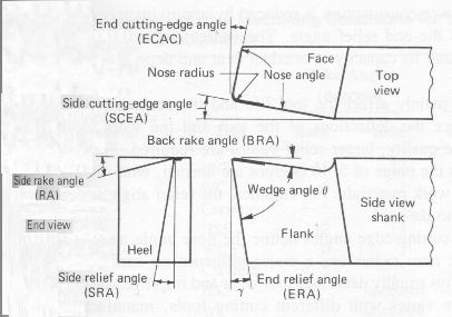
The back rake angle affects the ability of the tool to shear the work material and form the chip. It can be positive or negative. Positive rake angles reduce the cutting forces resulting in smaller deflections of the workpiece, tool holder, and machine. If the back rake angle is too large, the strength of the tool is reduced as well as its capacity to conduct heat. In machining hard work materials, the back rake angle must be small, even negative for carbide and diamond tools. The higher the hardness, the smaller the back rake angle. For high-speed steels, back rake angle is normally chosen in the positive range. There are two basic requirements for thread cutting. An accurately shaped and properly mounted tool is needed because thread cutting is a form-cutting operation. The resulting thread profile is determined by the shape of the tool and its position relative to the workpiece. The second by requirement is that the tool must move longitudinally in a specific relationship to the rotation of the workpiece, because this determines the lead of the thread. This requirement is met through the use of the lead screw and the split unit, which provide positive motion of the carriage relative to the rotation of the spindle.
Tool Geometry. For cutting tools, geometry depends mainly on
the properties of the tool material and the work material. The standard
terminology is shown in the following figure. For single point tools, the most
important angles are the rake angles and the end and side relief angles.
The back rake angle affects the ability of the tool to shear the work material and form the chip. It can be positive or negative. Positive rake angles reduce the cutting forces resulting in smaller deflections of the workpiece, tool holder, and machine. If the back rake angle is too large, the strength of the tool is reduced as well as its capacity to conduct heat. In machining hard work materials, the back rake angle must be small, even negative for carbide and diamond tools. The higher the hardness, the smaller the back rake angle. For high-speed steels, back rake angle is normally chosen in the positive range. There are two basic requirements for thread cutting. An accurately shaped and properly mounted tool is needed because thread cutting is a form-cutting operation. The resulting thread profile is determined by the shape of the tool and its position relative to the workpiece. The second by requirement is that the tool must move longitudinally in a specific relationship to the rotation of the workpiece, because this determines the lead of the thread. This requirement is met through the use of the lead screw and the split unit, which provide positive motion of the carriage relative to the rotation of the spindle.
Tool Geometry. For cutting tools, geometry depends mainly on
the properties of the tool material and the work material. The standard
terminology is shown in the following figure. For single point tools, the most
important angles are the rake angles and the end and side relief angles.
The back rake angle affects the ability of the tool to shear the work material and form the chip. It can be positive or negative. Positive rake angles reduce the cutting forces resulting in smaller deflections of the workpiece, tool holder, and machine. If the back rake angle is too large, the strength of the tool is reduced as well as its capacity to conduct heat. In machining hard work materials, the back rake angle must be small, even negative for carbide and diamond tools. The higher the hardness, the smaller the back rake angle. For high-speed steels, back rake angle is normally chosen in the positive range.
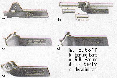
Most lathe operations are done with relatively simple, single-point cutting
tools. On right-hand and left-hand turning and facing tools, the cutting takes
place on the side of the tool; therefore the side rake angle is of primary
importance and deep cuts can be made. On the round-nose turning tools, cutoff
tools, finishing tools, and some threading tools, cutting takes place on or near
the end of the tool, and the back rake is therefore of importance. Such tools
are used with relatively light depths of cut. Because tool materials are
expensive, it is desirable to use as little as possible. It is essential, at the
same, that the cutting tool be supported in a strong, rigid manner to minimize
deflection and possible vibration. Consequently, lathe tools are supported in
various types of heavy, forged steel tool holders, as shown in the figure.
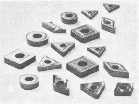
The tool bit should be clamped in the tool holder with minimum overhang. Otherwise, tool chatter and a poor surface finish may result. In the use of carbide, ceramic, or coated carbides for mass production work, throwaway inserts are used; these can be purchased in great variety of shapes, geometrics (nose radius, tool angle, and groove geometry), and sizes.
The turning machines are, of course, every kinds of lathes. Lathes used in
manufacturing can be classified as engine, turret, automatics, and numerical
control etc.
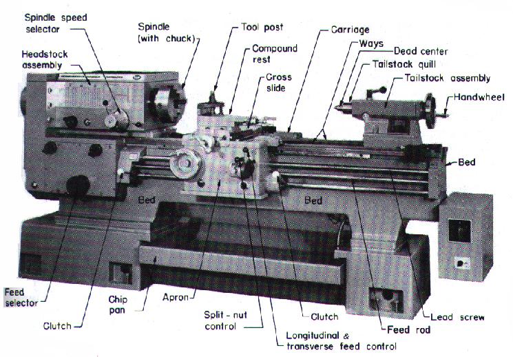
They are heavy duty machine tools and have power drive for all tool movements. They commonly range in size from 12 to 24 inches swing and from 24 to 48 inches center distance, but swings up to 50 inches and center distances up to 12 feet are not uncommon. Many engine lathes are equipped with chip pans and built-in coolant circulating system.
Turret Lathes. In a turret lathe, a longitudinally feedable,
hexagon turret replaces the tailstock. The turret, on which six tools can be
mounted, can be rotated about a vertical axis to bring each tool into operating
position, and the entire unit can be moved longitudinally, either annually or by
power, to provide feed for the tools. When the turret assembly is backed away
from the spindle by means of a capstan wheel, the turret indexes automatically
at the end of its movement thus bringing each of the six tools into operating
position. The square turret on the cross slide can be rotated manually about a
vertical axis to bring each of the four tools into operating position. On most
machines, the turret can be moved transversely, either manually or by power, by
means of the cross slide, and longitudinally through power or manual operation
of the carriage. In most cased, a fixed tool holder also is added to the back
end of the cross slide; this often carries a parting tool.
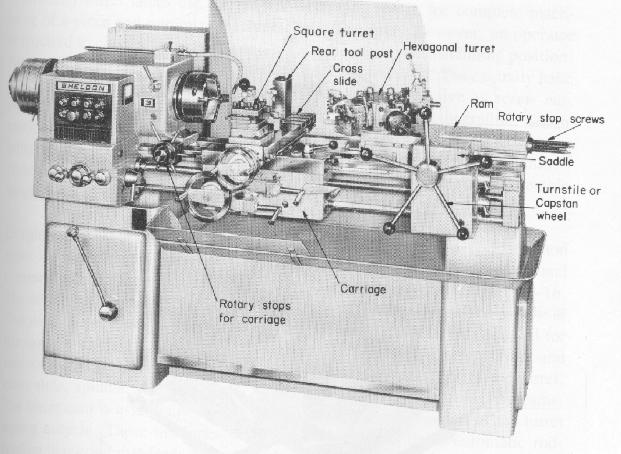
Through these basic features of a turret lathe, a number of tools can be set on the machine and then quickly be brought successively into working position so that a complete part can be machined without the necessity for further adjusting, changing tools, or making measurements.
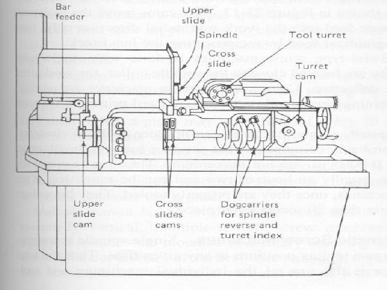
Single-Spindle Automatic Screw Machines. There are two common
types of single-spindle screw machines, One, an American development and
commonly called the turret type (Brown & Sharp), is shown in the following
figure. The other is of Swiss origin and is referred to as the swiss type. The
Brown & Sharp screw machine is essentially a small automatic turret lathe,
designed for bar stock, with the main turret mounted on the cross slide. All
motions of the turret, cross slide, spindle, chuck, and stock-feed mechanism are
controlled by cams. The turret cam is essentially a program that defines the
movement of the turret during a cycle. These machines usually are equipped with
an automatic rod feeding magazine that feeds a new length of bar stock into the
collect as soon as one rod is completely used.
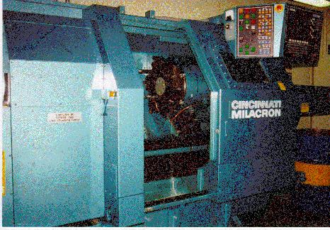
CNC Machines. Nowadays, more and more Computer Numerical
Controlled (CNC) machines are being used in every kinds of manufacturing
processes. In a CNC machine, functions like program storage, tool offset and
tool compensation, program-editing capability, various degree of computation,
and the ability to send and receive data from a variety of sources, including
remote locations can be easily realized through on board computer. The computer
can store multiple-part programs, recalling them as needed for different parts.
A CNC turret lathe in Michigan Technological University is shown in the
following picture.
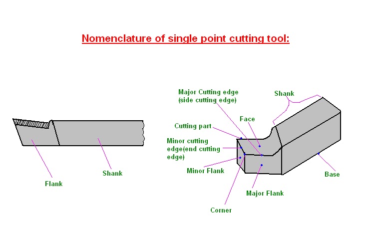
Angles of Single point cutting tool :

