Marking and marking tools

Marking the dimension point or line is important as placing and reading the rule properly.

- Angle divider

- Bevel protractor

A circle can be divided into 360 equal angles. Each angle is called degree. So a circle is 360 degrees (360o). For calculation a degree is divided into 60 parts called minutes and a minute is sub-divided into 60 parts called seconds.

The bevel protractor is used to establish and test angles to very close tolerances. It reads to 5 minutes or 1/20o and can be used completely through 360o.


Vernier bevel protractor


The bevel protractor consists of a beam, graduated dial and blade which is connected to swivel plate (with Vernier scale) by thumb nut and clamp.


Vernier bevel protractor - Parts


When the edges of the beam and blade are parallel, a small line on the swivel plate coincides with the zero line on the graduated dial, and when any measurement of an angle between the beam and the blade of 90 degrees or under is desired, the reading may be obtained direct from the position of the line on the swivel plate with regard to the graduation numbers on the dial. But remember this: To obtain the measurement of the angle between the beam and the blade of over 90 degrees subtract the number of degrees as indicated on the dial from 180 degrees. This is because, the dial is graduated from opposite zero marks to 90 degrees each way.


Vernier bevel protractor - Angles


Since the spaces, both on the main scale and the vernier scale, are numbered both to the right and to the left from zero, any angle can be measured. The readings can be taken either to the right or to the left, according to the direction in which the zero on the main scale is moved.

Picture below illustrates a variety of uses of the bevel protractor.


How to use Vernier bevel protractor

Reading the bevel protractor vernier scale:

The bevel protractor vernier scale indicates every five minutes or 1/20o of a degree. Each space on the vernier scale is 5 minutes less than two spaces on the main scale. Twenty four spaces on the vernier scale equal in extreme length twenty three double degrees. Thus, the difference between the space occupied by two degrees on a main scale and the space of the vernier scale is equal to one twenty fourth of two degrees or one twelfth of one degree (or five minutes).

Read off directly from the main scale the number of whole degrees between 0 on this scale and the 0 of the vernier scale. Then count, in the same direction, the number of spaces from the zero on the vernier scale to a line that coincides with a line on the main scale; multiply this number by 5 and the product will be the number of minutes to be added to the whole number of degrees.


Reading the bevel protractor Vernier scale
 
For example: Zero on the vernier scale has moved 28 whole degrees to the right of the 0 on the main scale and the 3th line on the vernier scale coincides with a line upon the main scale as indicated. Multiplying 3 by 5, the product, 15, is the number of minutes to be added to the whole number of degrees, thus indicating a setting of 28 degrees and 15 minutes.


- Center square and center line finder

The center square enables you to accurately locate the center of a round stock. Press the center square firmly against the side of the round stock and inscribe short line. Then rotate the center square approximately one third of the circumference of the round stock and mark a second line, intersecting the first. For accuracy the tool should be rotated once more and a third line made. The center of the work is indicated by the intersection of the lines. The same tool can be used to mark diagonals on square stock.


Wooden center square - How to use

Center square - How to use

Center square version 1


Wooden center square

Wooden center square plan

Center square version 2


Center square

Center square plan

CENTER LINE FINDER


Center line finder enables you to accurately locate center (middle) line of a board (edge, face or end). It’s very handy for marking the center of board edge when you’re laying out mortises, holes for dowels, centering biscuits, and doing plenty of other operations.


Center line finder - How to use

Large center line finder - How to use

Center line finder - Version 1


Center line finder

Center line finder plan

Center line finder - Version 2


Large center line finder

Large center line finder plan


- Centre punch

- Combination square

The combination square set consist of a blade (graduated steel rule) and moving heads called a square head, protractor and a center head.
Combination square

The blade is designed to allow the different heads to slide along the blade and be clamped at any desired location. By removing all the heads, the blade may be used alone as a rule or a straight edge. This tool, with its attachments, may be used for a great many purposes in framing and general work.

The blade (steel rule) can be used as a rule or a straight edge by itself or with any one of the following components.

The square head is designed with a 45 and 90 edge, which makes it possible to be used as a try square and miter square. It may also be used as a height or depth gage. The square head is also fitted with a level vial and a removable scriber.


Various uses of the combination square:


Combination square - Various uses of the square head


Laying out parallel lines with a combination square

The center head can be used to locate and lay out the exact center of round stock.


Combination square - Various uses of the center head


The protractor head can be used to mark off or measure any angle through 180. Angular graduations usually read from 0 to 180 degrees both ways, permitting the supplement of the angle to be read.


Combination square - Various uses of the protractor head


- Cutting gauge

- Dividers (Compasses)

- Dovetail marker

- Marking gauge

The marking gauge is used to mark lines parallel to the sides, edges, or ends of a board. The required distance is set by measuring from the point of marking spur to the head, or by taking a reading directly from the graduated scale on the beam. It consists of a head or stock and a bar or beam provided with a spur. The beam is fitted to the through mortise and is secured at any point in its length by the thumb nur or a wedge.

Marking gauge plan

Swedish marking gauge

Marking gauge with rectangular long stock and rectangular beam. The beam is held in place by wedges.


Swedish marking gauge

English marking gauge


English marking gauge differs from the Swedish one in having a thumb screw on one side of the stock, which works against the beam and holds it in position.


English marking gauge


By clamping the bar so as to bring the spur a given distance from the stock, a like distance may be gauged from any straight edge. The beam is usually graduated in milimeters or inches. The graduations on the beam are seldom reliable. It is safer to set the gauge with the rule by measuring the distance from the spur to the gauge head. This is done by holding the gauge bottom side up in the left hand. With the right place the end of the rule against the head. After the thumb screw has been tightened, apply the rule again to make sure of the correctness of the setting.
Setting the marking gauge with a ruler
To gauge the line, take the marking gauge in the right hand, three fingers grasping the beam, the first finger encircling the head, if the work is narrow, and the thumb back, or nearly back, of the spur. The head should be kept against one or the other of the faces. Begin at the end of the piece which is towards you, hold the block firmly against the piece, roll the beam forward until the spur barely touches the surface, and make a very light line. Avoid deep lines; they are inaccurate even if straight and always cause trouble in the making unless the grain of the wood is perfectly straight.
Marking gauge - Marking paraller lines
Marking gage are excellent for repeating dimension lines. You can repeat marking as often as you wish.


Marking gauge - You can repeat marking as often as you wish

Roll the marking gage so the spur just touches the surface for a light gauge line.


Roll the marking gauge so the spur just touches the surface

The spur of a marking gauge may be sharpened to a conical point or to a knife edge.


Marking gauge - Spur sharpened to a conical point or to a knife edge.


The spur should be sharp to do good work. If sharpening is necessary, loosen the set screw, remove the spur, and file or grid. If sharpened to a knife edge, the edge of the spur should be set parallel with the head of the gauge. Tighten the setscrew to hold the adjusted pin securely.
Marking gauges consist of two main parts, a fence and a stem. The stem carries a pointed metal spur at the end. The fence can be fixed to any position along the stem by a wedge. Marking gauge is an essential tool for basic carpentry and joinery. It is used to score a single line parallel to the face side or face edge, when planning a piece of timber to size, and for marking out rabates and simple joints. The spur is simply a nail with its head cut off and hammered into the end of the stem.


Marking gauge plan


DOWNLOAD COMPLETE PLAN:

Marking gauge plan ( PDF ) - Pages 8; 752Kb

Marking gauge plan - Parts List

Marking gauge plan - Assembly Drawing

Using the Marking gauge


To use the gauge first set the distance from the spur to the fence. Tighten the fence to the stem by tapping the back of the wedge with a piece of wood. Check the setting and make final adjustments by tapping either end of the stemon the bench top. To loosen the fence tap the front of the wedge.


DOWNLOAD COMPLETE PLAN:

Marking gauge plan ( PDF ) - Pages 8; 752Kb

- Miter (mitre) square

- Mortise gauge

- Odd leg caliper

- Panel gauge

The panel gauge is used for making lines at a greater distance from the working edge. The stem and fence are longer than those of the marking gauge, but otherwise does not differ from the marking gage.

This is a large wooden gauge with a wide fence and a stem anything up to a metre long. Instead of the workpiece being marked with a metal spur, the stem carries a pencil, located in a hole at the one end. The fence and the stem are locked together by a wedge.

This type of gauge is used for marking out wide panels of timber or plywood. The lower edge of the fence is rabated on one side, which helps to keep it firmly in contact with the edge of the board to be marked.


Panel Gauge plan

DOWNLOAD COMPLETE PLAN:

Panel gauge plan ( PDF ) - Pages 8; 747Kb

Panel gauge plan - parts list

Panel gauge plan - parts list

Panel gauge plan - Assembly drawing
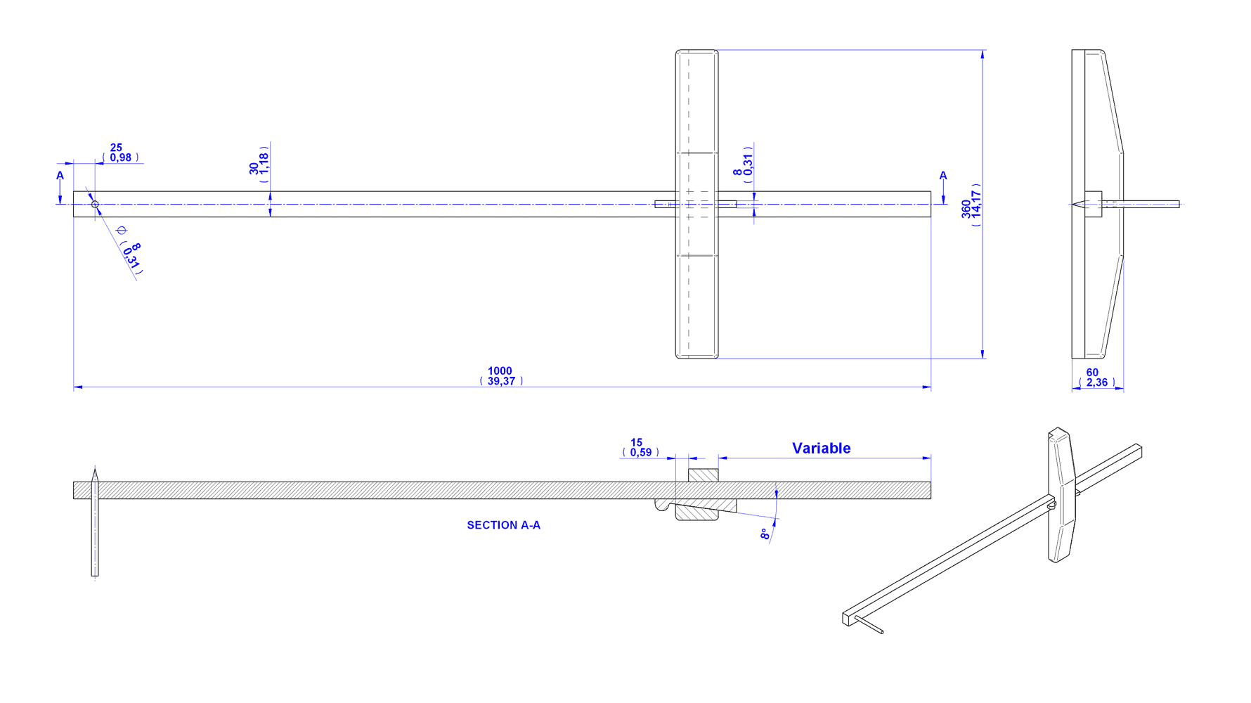
Panel gauge plan - Assembly drawing

Using the Panel gauge

Set the distance between the pencil and the fence with a ruler. Tighten the fence by hitting the back of the wedge with a piece of wood or a small hammer. Loosen the fence by hitting the front of the wedge.


DOWNLOAD COMPLETE PLAN:

Panel gauge plan ( PDF ) - Pages 8; 747Kb

- Plumb bob

- Scriber

- Sliding T bevel

In many cases it is necessary to test the relation of lines and surfaces which are not at right angles to each other. For this purpose a sliding bevel is used. The sliding bevel differs from the try square in having a movable blade. This blade may be set at any desired angle from 0 to 180 degrees. A locking screw secures the blade tight at any angle.

The sliding bevel is used for laying out angles other than 90 degrees and for testing constructed angles. The sliding bevel may be made entirely of steel or wood or it may have a stock of wood and a blade of steel.

Make sliding T bevel - Sliding T bevel plan


Sliding T bevel

There are various ways of setting the sliding bevel to the required angle.

Setting to a drafting triangle

Should the triangle used in drafting be available, angles of 30 degrees, 45 degrees and 60 degrees are easily obtained by adjusting the sliding bevel to the sides of the required angle.


Sliding T bevel - Sertting to a drafting triangle

Setting to a framing square

To set the bevel at a miter (an angle of 45 degrees), place the stock against one leg of the framing square and adjust the blade so that it will agree with equal distances on both legs, as 5cm and 5cm. Any distances may be taken, but it must be the same on both legs.


Sliding T bevel - Setting to a framing square

Setting to a protractor

Slacken the locking screw enough to allow the blade to be moved. Hold the stock against the base of the protractor, set the blade to the required angle and tighten the locking screw.


Sliding T bevel - Setting to a protractor

Testing constructed angle

To test a chamfer or bevel for trueness, set the sliding bevel to the required angle. Move the sliding bevel along the object to check more than one place.


Sliding T bevel - Testing constructed angle

Make sliding T bevel - Sliding T bevel plan


- Steel square

The steel square is often called the carpenter’s square or framing square. The steel square is used in measuring boards, testing corners, and seting the bevel of boards and tools to various angles.

It is made of steel, having two flat blades at right angles to each other an having measuring scales on every edge. The long side of the steel square is known as the blade (or body) and the short side as the tongue. The chief value of this tool to the bench worker lies in the fact that it is much better than a try square for use on large work. The edges also are often used as straight edges in laying out work.


Steel (framing) square
A steel (framing) square can be used for laying out angles by foloving the illustration and table below. The pivot point for measuring these angles is the 100mm mark on the tongue of the square.


A steel (framing) square can by used for laying out angles
To make a square (90o) mark, place the tongue along or against one edge of the stock. Mark along outside edge of the blade on the face of the stock.


Steel (framing) square - Make a square mark

To lay out a 45o angle, place the steel square on the face of the stock so that an equal number of graduations on the blade and on the tongue fall on the stock.


Steel (framing) square - Make a 45 degrees mark


To set an angle of 45 degrees by measurement, use the steel square and sliding T bevel. Equal distances on the blade and tongue will give an angle of 45 degrees.


To set an angle of 45 degrees by mesurement - Steels square and sliding bevel
If a steel (framing ) square is suspected of not being accurate, it may be tested easily. Use a board that has a perfectly straight edge

- Place the tongue (or blade) of the steel square against a perfectly straight edge of a board which is wide enough to allow a pencil line to be made the entire length of the blade. Draw a line across the face along the blade of the steel square. (picture A)

- Turn the steel square over (picture B)

- Holding the tongue against the same straight edge, move the blade to the previously marked line (picture C)

- If the steel square is accurate, the pencil line and the edge of the blade will perfectly coincide. (picture D)


Testing a steel (framing) square


- Surface gauge

- Surface plate

- Trammel

- Triangle

- Try square

The try square has a blade (straight edge) and a stock (beam) which are fixed together at exactly 90. The stock is much thicker than the blade. The edge of the blade and the stock are perfectly sharp and straight.

Try square plan

Try square - Marking hand tool


The try square may be made entirely of steel or wood or it may have a stock of wood and a blade of steel. The blade have metric or imperial graduations or a combination of both.

The try square is used mostly for:

- Laying out lines perpendicular to an edge or side of a board

- Checking edges and ends of boards to see if they are square with adjoining surfaces

- Checking the width or thickness of narrow boards

- Measuring short distances

- Checking flatness


Marking on a edge a with try square Marking on a side a with try square
Marking on a edge Marking on a side
   
Checking outside corner a with try square Checking inside corner a with try square
Checking outside corner Checking inside corner
   
Checking flatness with a try square Measuring short distances with a try square
Checking flatness Measuring short distances

In order to keep the try square accurate, care should be taken not to drop it. All the angles of the square, exterior as well as interior, must be perfect right angles.

If a try square is suspected of not being accurate, it may be tested easily. Use a board that has a perfectly straight edge

- Place the stock of the try square against a perfectly straight edge of a board which is wide enough to allow a pencil line to be made the entire length of the blade. Draw a line across the face along the blade of the try square. (picture A)

- Turn the try square over (picture B)

- Holding the stock against the same straight edge, move the blade to the previously marked line (picture C)

- If the try square is accurate, the pencil line and the edge of the blade will perfectly coincide. (picture D)


Testing try square accuracy

Always keep the try square at right angles to the surface.


Try square - Wrong use

ENGINEER’S (MACHINIST) SQUARE

A engineer's square (machinist square) is the metalworkers' equivalent of a try square. Machinist try squares are made entirely from metal to guarantee accuracy. A notch is cut in the stock in line with the inside edge of the blade for accurate measurement even when there is a burr on the edge of the work.


Engineer's (Machinist) square

Try square plan


Try squares made of wood are very practical pieces of equipment, and are quick and easy to make. They can be made to any size up to a metre in length. Use the dimension given here only as a guide. When making this tool it is most important that the straight edge and the stock are glued up perfectly square, otherwise all the woork done with it will be inaccurate.


The try square is used mostly for:

- Laying out lines perpendicular to an edge or side of a board

- Checking edges and ends of boards to see if they are square with adjoining surfaces

- Checking the width or thickness of narrow boards

- Measuring short distances

- Checking flatness


Try square plan

DOWNLOAD COMPLETE PLAN:

Try square plan ( PDF ) - Pages 7; 744Kb

Try square - how to use

Try square plan - Parts list
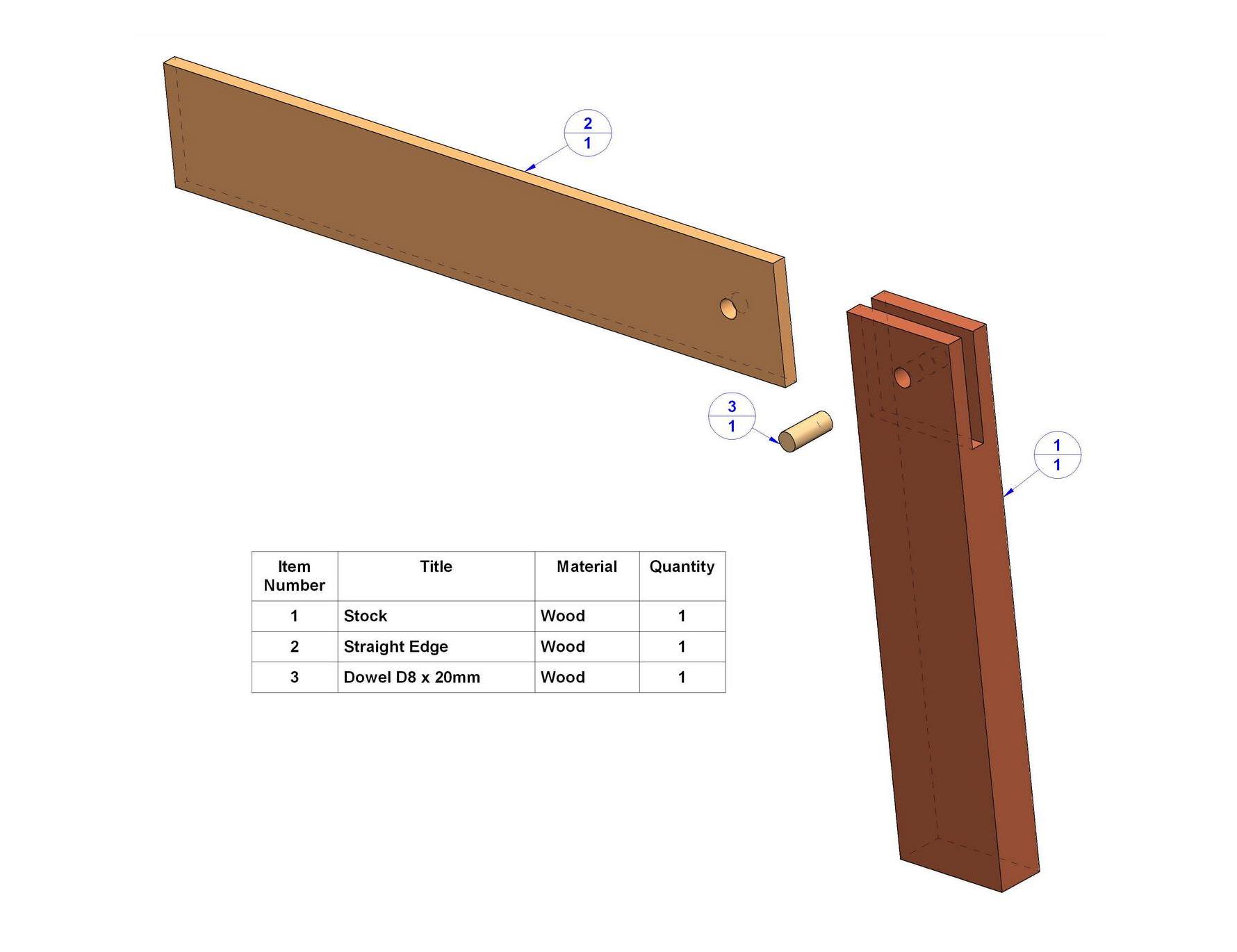
Try square plan - Parts list

Try square plan - Assembly drawing

Try square plan - Assembly drawing

DOWNLOAD COMPLETE PLAN:

Try square plan ( PDF ) - Pages 7; 744Kb