Measuring and marking
The Woodworkers Try-Square
 |
The woodworkers try-square is composed of two main parts -
the stock and the blade. The blade is made from hardened and tempered steel
which makes is resistant to damage. The stock is usually made from rosewood
although cheaper versions can be made from plastic or cheap woods.
A brass face is added to the stock to ensure a straight edge. |
| |
|
|

|
A typical use of a woodworkers try-square can be seen
opposite.
The try-square is pushed against the straight edge of a piece of wood and a
marking knife is then used to mark a straight line across the material. The
line is continued all the way round the wood (all four sides are marked).
This type of marking materials helps if a joint is to be cut or the end of
the material is simply to be sawn away. |
 |
An alternative use of a try-square is to test the edge of
a piece of wood to check how square it is (has it got a 90 degree angle
along its length?). The try-square and material are held up to the light and
the try-square is moved along the length of the wood. If light shines
through any gaps between the blade and the wood, then the edge is not
square. |
The Marking Gauge
|
A marking gauge is used to mark a line parallel to a
straight edge. The stem and stock are made from beech and the thumbscrew
from clear yellow plastic. The better quality gauges have brass inserts at
the front of the stock. These help reduce the wear on the stock as it is
pushed against the surface of the wood - to be marked. The marking gauge is
an extremely important tool for marking parallel lines and preparing for
cutting joints. |
|
| |
|
|
 |
| |
|
|
The gauge has a sharp point called a spur. This is made from hardened steel and is
the part that ‘scribes’ the line into the surface of the wood. The distance
between the stock and the spur can be adjusted by loosening the thumbscrew
which allows the stock to slide along the stem. The thumbscrew can then be
tightened once the correct distance has been reached. A ruler is used to set
the distance (see diagram opposite).
If the spur is replaced with a small knife it is now called a cutting gauge and is used for cutting lines
into solid wood surfaces in preparation for veneering or inlaying. |
 |
|
ALTERING THE DISTANCE
BETWEEN THE SPUR AND STOCK |
| |
|
|
|
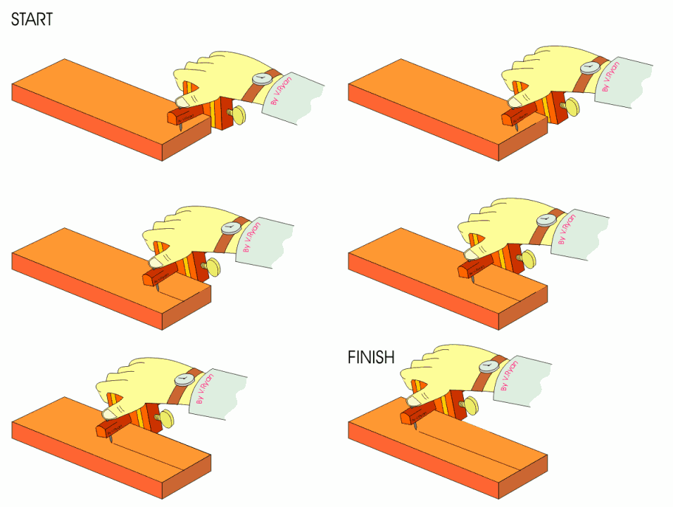
MARKING WITH THE GAUGE
The wood is held firmly to the bench by a G cramp or
bench hook. The stock of the marking gauge is pressed firmly against a
straight edge of the wood and pushed carefully along it. A little pressure
is applied to the spur, too much pressure and the spur digs into the wood
marking an ugly line on the surface.
It is a good idea to lightly scribe a line along the surface first and then
repeat the process two or three times until an accurate scribed line can be
seen. |
|
| |
|
|
 |
The Engineers Try-Square
|

|
The engineers try-square is composed of two parts, the
stock and the blade. They are usually made from bright mild steel with the
blade being hardened and tempered so that it resists damage.
It is normally used during engineering / metalworking projects |
| |
|
|

|
A typical use of an engineers try-square is to mark out
material for cutting/shaping.
The try square is pushed against a straight side of the material (eg.
steel). An engineers scriber is then used to scratch a line onto the surface
of the metal. Sometimes engineers blue (a dye/ink) is wiped onto the surface
first so that the scratched line can be seen easily. The material is then
cut down to this straight line. |
|

|
Look closely at an engineers try-square, you should see
an interesting feature. There should be a small slot that has been cut into
the stock. This prevents small burrs caused by filing from altering the
try-squares accuracy. Dirt can also collect on metal surfaces, again the
slot helps prevent measuring angles inaccurately.
In the example seen opposite, the try-square is used to test that a 90
degree angle exists across the edge of the steel. Although a burr exists on
the edge of the steel it fits into the slot and does not affect the way the
try-square is used. |
The Sliding Bevel
|

|
The sliding bevel is composed of two parts, the stock and
the blade. The stock is usually made from rosewood which is a high quality
material. The blade is made from hardened and tempered steel. The blade can
be adjusted to a variety of angles and locked in position. This is useful
when a line has to be marked at an angle on wood.
A typical use is seen below. |
| |
|
|
1. The stock of the sliding bevel is held firmly against
the wood and the lock is loosened allowing the angle of the blade to be
altered.
2. The lock on the sliding bevel is tightened so that the
angle of the blade cannot be altered accidentally. A marking knife is used
to mark a line at the correct angle.
3. The wood is cut to the correct angle using a
saw/fretsaw or appropriate tool. |
 |
How to use a Centre Square
|
|
A Centre Square can be used to find the centre of a
piece of round material. It is virtually impossible to do this through
guess work. The centre square is probably one of the simplest tools ever
designed as it is composed of only two pieces of material. When placed up
against a round piece of material such as a round section of steel it can
be used to find the centre accurately. |
| The procedure
for using the centre square to find the centre of round section material is
seen below. |
| |
 |
| |
The technique is straight forward.
1. Place the centre square against the round section material.
2. Draw/scribe a line right across it.
3. Rotate the round material a little and draw/scribe a line again.
Where the two lines cross is the centre of the material. |
|
How to use a Surface Gauge
| |
| |
|
A surface gauge is very useful when finding the centre of
a piece of round section material. It is normally used to ‘scribe’ parallel
lines. Its base is heavy and this means it is stable when in used. Surface
gauges sometimes have magnetic bases and this means they can be locked onto
metal surfaces making it easier to use. |
 |
| |
| |
|
A surface gauge is very useful when finding the centre of
a piece of round section material. It is normally used to ‘scribe’ parallel
lines. Its base is heavy and this means it is stable when in used. Surface
gauges sometimes have magnetic bases and this means they can be locked onto
metal surfaces making it easier to use. |
 |
|
|
| |
|
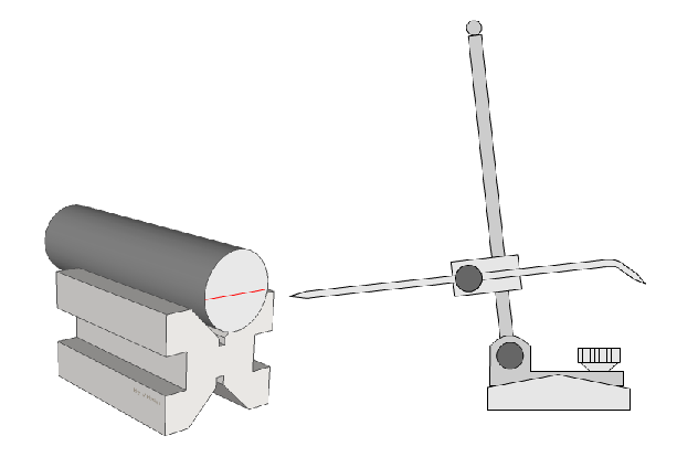
The diagram above shows the round section steel held in a vee block. The
surface gauge is then moved across the surface of the steel, scribing a
line. The steel is then rotated through 90 degrees and another line is
scribed. This is repeated until a square is produced in the centre (see
diagrams below). Diagonal lines are then drawn from each corner of the
square to locate the exact centre of the circle.
|
| |
|
The Centre and Dot Punch
|

|
The centre punch is made form mild steel with the point
hardened and tempered so that it withstands impact with the material it is
marking. It is normally used to mark the centre of a hole to be drilled
either by hand or on the drilling machine.
The dot punch is a lighter and thinner version of the centre punch and is
used basically for the same job. However, it is more accurately as the dot
produced is smaller. |

Both the centre and dot punches are used in the same way. A
ball pein hammer is used to tap the head of the punch and this delivers enough
force to the point of the punch to put a small indentation into the surface of
the material.
The Mortise Gauge
|
The mortise gauge is a special type of marking gauge and
it is used to mark wood so that a mortise can be cut into it. The diagram to
the right represents a typical mortise and tenon joint. The mortise is
marked out using the mortise gauge although it must be set to the correct
size of mortise chisel very carefully. A mortise chisel is then used to
remove the waste wood.
The mortise gauge is normally made from a hardwood such as rose wood with
brass being used for the parts that slide along the stem. |
 |
| |
|
|
 |
|
 |
1. The distance
between the fixed spur and the adjustable spur is set so that it matches the
width of the mortise chisel. This done by turning the brass thumb screw. The
width of the mortise chisel should match the width of the mortise to be cut
in the wood. |
| |
|
|
2. A try square and a
marking knife are used mark the lines at the top and bottom of the mortise. |
 |
|
 |
3. The stock of the
mortise gauge is pressed against the side of the wood. It is then pushed
along the wood until the mortise is marked out correctly. |
|
4. The mortise
chisel is then used to break the surface of the waste wood by gently
tapping the handle with a mallet. |
|
5. The waste
wood is then slowly removed, this time, by applying more force to the
handle of the chisel with the mallet. The waste is removed until the
entire mortise hole has been cut. |
|
|
 |
An accurate ruler with metric markings.
If you are buying one specially I would recommend the thin flexible steel
rulers. But a decent plastic ruler will be fine.
Marking gauge


International System of Units
The International System of Units is the modern form of
the metric system and is generally a system devised around the convenience of
the number ten. It is the world's most widely used system of measurement, both
in everyday commerce and in science.
The older metric system included several groups of units. The SI was
developed in 1960 from the old metre-kilogram-second system. Because the SI is
not static, units are created and definitions are modified through
international agreement among many nations as the technology of measurement
progresses, and as the precision of measurements improves.
The system is nearly universally employed. Three principal exceptions are
Burma (Myanmar), Liberia, and the United States. The United Kingdom has
officially adopted the International System of Units but not with the
intention of replacing customary measures entirely.
There are seven base units of the SI:
METRE (m) - The metre is the length of the path travelled
by light in vacuum during a time interval of 1/299 792 458 of a second.
KILOGRAM (kg) - The kilogram is the unit of mass; it is
equal to the mass of the international prototype of the kilogram.
SECOND (s) - The second is the duration of 9 192 631 770
periods of the radiation corresponding to the transition between the two
hyperfine levels of the ground state of the caesium 133 atom.
AMPERE (A) - The ampere is that constant current which, if
maintained in two straight parallel conductors of infinite length, of
negligible circular cross-section, and placed 1 m apart in vacuum, would
produce between these conductors a force equal to 2 x 10⁻⁷ newton per metre of
length.
KELVIN (K) - The kelvin, unit of thermodynamic
temperature, is the fraction 1/273.16 of the thermodynamic temperature of the
triple point of water.
MOLE (mol) – The mole is the amount of substance of a
system which contains as many elementary entities as there are atoms in 0.012
kilogram of carbon 12.
CANDELA (cd) - The candela is the luminous intensity, in a
given direction, of a source that emits monochromatic radiation of frequency
540 x 1012 hertz and that has a radiant intensity in that direction of 1/683
watt per steradian.
A prefix may be added to a unit to produce a multiple of the original unit.
All multiples are integer powers of ten.

SI derived unit
The International System of Units (SI) specifies a set of seven base units
from which all other units of measurement are formed. These units are called SI
derived units and are also considered part of the standard.
Other common units, such as the litre, are not SI units, but are accepted for
use with SI
Read more:
- Wikipedia website
- BIPM - Bureau
International des Poids et Mesures
The Greek alphabet is a set of twenty-four letters that has
been used to write the Greek language since the late 9th or early 8th century
BCE. It is the first and oldest alphabet in the narrow sense that it notes each
vowel and consonant with a separate symbol. It is as such in continuous use to
this day. The letters were also used to represent Greek numerals, beginning in
the 2nd century BCE.
Greek symbols are traditionally used as names in mathematics, physics and
other sciences. When combined with Latin characters, the Latin characters
usually indicate variables while the Greek ones indicate parameters. Many
symbols have traditional meanings, such as lower case alpha (α) for angle of
attack in fluid dynamics, lower case epsilon (ε) for `a small number, which
tends towards the infinitesimal', capital sigma (Σ) for `sum', and lower case
sigma (σ) for standard deviation.
Measuring and measuring tools
Accurate measurement is the basis of good engineering and crafting practice.
The accuracy of any measuring device depends on the user as much as on the
design of the tool.
Measuring is not only checking the length, width or thickness of an objects
but also checking of the shape – things like the flatness, straightness,
roundness or squareness. Measuring tools are also used for inspecting a
finished or partly finished product.
All measuring tools are precision tools. You must take good care of them to
keep them in good shape to maintain accuracy.
There are two systems of measurement. The traditional system used in the
United States is the US customary system. It is based on the English imperial
system of measure. The second is called the SI system (Metric system). The
metric system is an
international decimalised system of measurement, first adopted by
France in 1791, that is the common system of measuring units used by most of
the world. All measuring tools have metric or imperial graduations or a
combination of both. One big advantage of the metric scale is that it
eliminates the necessity for a range of fractional sizes. The markings on a
metric rule are every millimetre with the figures marked at 10mm intervals.
Fractions are not used in the SI system.
There are many different types of measuring tools.
The most common, and the best known, piece of measuring equipment is the
ordinary rule.
The rule or tape is used for measuring where accuracy is not an extremely
critical factor. They can be rigid or flexible, come in various lengths, and
can be made of wood, metal, cloth, fiberglass...
A ruler, or rule, is an instrument used in geometry, technical drawing and
engineering/building to measure distances and/or to rule straight lines.
Warning: Measure twice, cut once.
Considerable frustration and additional expense can be avoided by checking for
a second time that the required measurement is accurately marked.
Rules may be flexible or nonflexible, but the thinner the rule, the easier
it is to measure accurately because the division marks are closer to the work.
Store rules carefully. If the edges and ends are damaged, there will be
inaccuracies. Many rules have a hole in one end so they can be hung up out of
harm’s way
A 150mm (6 inch) and a 300mm (12 inch) rule with both metric and imperial
markings will cover most needs.
The rule can also be used as a straight edge.
HOW TO USE THE RULE
Put the rule flat on object and read the measurement from the rule.
Keep the rule at a right angle to the object.
Read the measurement from directly above the rule.
In making several small measurements do not move the rule.
If the ruler is thicker
To measure and mark distances for accurate work, lay the rule on edge so that
the divisions on its side touch the stock.
If the end of the rule is inaccurate, start measuring at the 1cm mark.
Measuring outside diameter of a pipe
Measuring inside diameter of a pipe
Measuring the length of a bolt or screw
Whenever there are several measurements to be made along a straight line, the
rule should not be raised until all are made, for with each placing of the
rule errors are likely to occur.
The rule is used to find the middle of an edge by placing it across the
piece so that the distances from the edges of the piece to corresponding
fractional marks, shall be the same. The middle of the piece being at a point
midway between the marks selected.
Next image illustrates a second method of finding middle of a piece. Lay the
rule across the piece at an angle such that two of the unit marks shall rest
each upon an arris. The middle of the piece will then be at that unit mark
which is midway between these.
If it is desired to divide a piece into more than two parts lay the rule
across the piece at such an angle as will bring two of its unit marks each
upon an arris with the required number of divisions between. Next image shows
a piece divided into three equal parts.
Wooden rulers (Bench rulers)
Wooden rule is the woodworker’s traditional measuring instrument. The rule
itself is made from hardwood and is marked out in metric (millimetres) or
imperial (inches); some rules have both.
The wooden rule doaes have some disadvantages:
- It can be broken quite easily
- Its edges can be damaged through regular use affecting the accuracy of your
measurement
Steel rules (Engineer’s steel rules)
A steel rule is essential for any kind of metal work and is also a useful tool
in the woodwork workshop. The steel rule is much more versatile and durable
than wooden rule. Steel rules should be oiled to prevent rusting when not in
use. Steel rules may be flexible or non flexible, but the thinner the rule,
the easier it is to measure accurately because the division marks are closer
to the work.
Folding rules (Zig – zag rule, jointed rule, surveyor’s rod)
The folding rule can be used in a confined space where a long rule would be
inconvenient. It also overcomes the problem of carrying a long measuring rod to
the workplace. It is the rule most often used by carpenters. Folding rule is
made from hardwood and reinforces at the ends with brass. The rule is usually
made from strips, hinged in pairs to fold back on one another.
The folding rules cannot be relied on for extremely accurate measurements
because a certain amount of play develops at the joints after continued use.
Extension rules
The extension rule is a folding rule which includes a brass slide for making
internal measurements. The slide can also be used as a depth gauge. The slide
extends from the first strip of the rule
Steel tape (tape measure, push – pull steel tape, flexible rule,
retractable steel tape measure, flex tapes)

The steel tape measure is an extendable steel strip coiled into a container.
The tape is spring loaded. So that as soon as it is released it will
automatically return to the case.
Steel tapes are made from 2m to about 10m in length. The shorter tapes are
made with a curved, but rigid, cross section flexible enough to be rolled up.
Long, flat tapes need support over their full length to avoid sagging. Lack of
support can cause reading errors.
There are many tapes made to suit special needs. The steel tape is made of
flexible spring steel. Pocket steel tapes (push – pull steel tape) are shorter
types of steel tapes. The flexible rigid push pull steel tapes are usually
contained in metal or plastic cases into which they wind themselves when a
button is presses, or into which they can be easily pressed. A hook is
provided at one end to hook over the object being measured so one man can
handle it. The graduations are printed on only one face of the tape.
A good tape will retract automatically and smoothly.
Wind up tape measuring
The wind up tape measure is primarily designed for measuring large
dimensions, such as the size of a room.
Soft ruler (soft tape measure)
A tape measure or measuring tape is a flexible form of ruler. It consists of a
ribbon of cloth, plastic, or fiber glass strip with linear-measurement
markings.
Tape measures that were intended for use in tailoring or dressmaking were
made from flexible cloth or plastic.
CARE OF RULES AND TAPES
1. Keep rules and tapes clean and dry.
2. Store rules and tapes where they will not become bent or damaged.
The
metric system is based upon multiples of ten.
The metre is divided into 100 equal parts. One hundredth part of a metre is
called a centimetre (cm). So a hundred centimetres make one metre. Again a
centimetre is divided into ten equal parts called millimetres (mm). 10
millimetres make 1 centimetre, 100 centimetres make 1 metre.
Now let’s look at a section of the rule between 4 cm and 5 cm.
There are 10 equal divisions which are equal to 1/10 cm or 1 mm.
To measure 44 mm, first locate the longest line designated 4 cm or 40 mm.
Next count 4 additional lines to find 44 mm.
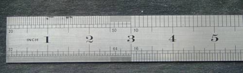
Generally, a imperial rule usually has four sets of graduations, one on each
edge of each side. The longest lines represent the inch marks. On one edge
each inch is divided into 8 equal spaces so each space represents 1/8 in. The
other edge of this side is divided in sixteenths. The 1/4-in. And 1/2-in.
marks are commonly made longer than the smaller division marks to facilitate
counting, but the graduations are usually not numbered individually, as they
are sufficiently far apart to be counted without difficulty. The opposite side
is similarly divided into 32 and 64 spaces per inch, and it is common practice
to number every fourth division for easier reading.

Look at the rule scale above. There is a small numeral marked on the end of
the rule (red numbers). This numeral indicates the number of divisions per
inch. When referring to fractions, always use the reduced name.
Look at the section between the “5” and the “6” on the edge marked with an
“8” for eighths. There are eight equally spaced lines. The lengths of these
lines differ and indicate different fractions or parts of an inch.
Each half inch is divided in half by a slightly shorter line indicating 1/4
on the left and 3/4 on the right.
Each 1/4 inch is divided in half by the shortest line which indicates 1/8
inch.
Now turn the rule and look at the edge with a 16 marked on it.
There are now 16 equal divisions between each inch. Common tapes and rules
usually are not graduated smaller than sixteenths. However, precision
measurements require smaller graduations.
Look at the back of the rule. Find the edge marked 32 and once again look
between the numbers “5” and “6”.
To read 5-5/8 inches on the scale, first find the five inch mark, then
determine the number of 32nds in 5/8.
If 1/8 = 4/32, then 5/8 = 20/32
(4 x 5 = 20)
1. Find the 20/32 reading on the scale as shown above.
2. Write the new fraction 5-20/32 inches.
In geometry, a protractor is a circular or semicircular tool for measuring an
angle or a circle.
In geometry, a protractor is a circular or semicircular tool for measuring an
angle or a circle. The units of measurement utilized are usually degrees.
You can draw any angle with the aid of a protractor. But make sure that you
measure the angle from line A-A and not from line B-B.
The protractor is also used to set angle on a sliding bevel.
A simple and inexpensive protractor such as is used in schools should be
suitable for most projects. Bear in mind, however, that the larger the
protractor, the more accurate the measurements are likely to be.
These tools are comparators, used for transfering a dimension from one place
to another.
These tools are comparators, used for transfering a dimension from one place
to another. Calipers can be set from a sample of work, from a rule or from a
micrometer. Most accurate setting can be obtained from a sample piece of work.
Quite accurate rasults can be obtained by setting calipers from micrometer.
The caliper legs should move smoothly but not too easily.
SIMPLE CALIPERS
Outside calipers (Bow calipers, egg calipers)
Outside calipers are used to measure the external size of an object. To adjust
a caliper to the work, open the legs wider than the work and then bring them
down to the work.
Setting to required dimensions
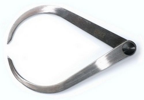
Inside calipers (Straight calipers)
Inside calipers are available in the same size range as outside calipers. They
have straight legs, turned out at the top and are used to take inside
measurements.
Setting to required dimensions
To adjust a caliper to a scale dimension, one leg of the caliper should be
held firmly against one end of the scale and the other leg adjusted to the
desired dimension.
Spring joint calipers
The spring joint calipers have legs pivoted on a roller and the legs are
tensioned by means of a strong bow spring. The adjustment for measuring is
made by opening and closing the legs by means of an adjusting nut.
Transfer calipers
Transfer calipers are used for measuring chamfered grooves or flanges. A screw
attaches a small auxiliary leaf to one of the caliper legs. The measurement is
made as with ordinary calipers. The leaf is locked to the leg. The legs may be
opened or closed as needed to clear the obstruction. The legs are then brought
back and locked to the leaf, restoring them to the original setting.
Inside/outside calipers (Combination calipers)
Odd leg calipers (hermaphrodite calipers, Jenny calipers)
Odd leg calipers are used to draw lines parallel to an edge. They consist of
one caliper leg and an leg with an adjustable scriber point. Odd leg calipers
can also be used to lay out the center of round stock.
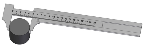
Slide caliper can be used for measuring outside and inside dimensions.
Slide caliper can be used for measuring outside and inside dimensions.
Graduations are in inches, fractions, or millimeters. The Slide caliper is
made as a separate rule or it is incorporated in a folding rule like the
extension on a extension rule.
1. Slide
2. Line for internal measurement
3. Clamp nut
To measure the inside diameter of a hole, or distance between two surfaces,
insert only the rounded tips of the caliper jaws into the hole or between two
surfaces. Read the measurement.
To measure the outside diameter of round stock, or the thickness of flat
stock, move the jaws of the caliper into firm contact with the surface of the
stock. Read the measurement.
The Slide caliper should not be used to measure the outside diameter of a
cylinder having a radius greater than the depth of the caliper opening.
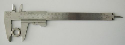
Vernier calipers are used for more accurate measuring than can be achieved
with a measuring rule or a slide caliper.

Vernier calipers work like slide caliper.
Vernier calipers are used for more accurate
measuring than can be achieved with a measuring rule
or a slide caliper. It is capable of measuring
internal and external dimensions and can also be
used as a depth gauge. Vernier calipers are
available with metric and imperial graduations.
1. External jaw
2. Intenal jaw
3. Sliding jaws
4. Metric Vernier scale
5. Locking screw
6. Main scale
7. Depth gauge
1. Measuring external dimensions
2. Measuring internal dimensions
3. Measuring depth dimensions
MEASURING WITH METRIC VERNIER CALIPER TO
WITHIN 0,02mm
Each division on the main scale is 1mm.
The metric vernier scale is 49mm long and divided
into 50 equal parts. Each division is 49/50, which
is equal to 0,98mm. The difference between one
division on the main scale and one division on the
metric vernier scale is 1/50 or 0,02mm.
Read the measurement as shown above.
To read the measurement note the main scale
measurement immediately preceding the zero line on
vernier scale.
The zero of the vernier scale immediately
preceding 28mm.
To this (28mm) must be added the decimal reading
on the vernier scale. Note the line on the vernier
scale which is coincident with a line on the main
scale.
30th line concides with a line on the main scale.
So the reading is 28mm plus 30 divisions of
0,02mm
TOTAL: 28mm + 30 * 0,02 = 28,6mm
MEASURING WITH IMPERIAL VERNIER CALIPER
TO WITHIN 0,001in
The main scale on the vernier is graduated and
numbered in inches with each inch graduated and
numbered in tenths (0,1in). Each tenth is divided
into four giving 0,1in. divided by 4 = 0,025in. On
the vernier scale 0,6in is divided into 25 parts.
Each of these has a length of 0,6in divided by 25 =
0,024in. The difference in length between a small
division on the main scale and the vernier scale is
0,025- 0,024 = 0,001in.
Read the measurement as shown above.
To read a measurement note the position of the
zero line on the vernier scale in relation to the
main scale. This is shown as 3,00in plus 0,300in
plus 2*0,025in which equals 3,35in. To this must be
added the number of divisions from the zero line on
the vernier scale to the line which is coincident
witha line on the main scale, in this case 15
divisions which equals 0,015in the total reading is
therefore:
Main scale = 3,35in
Vernier scale = 0,015in
So the reading is 3,35in + 0,015 = 3,365in
The vernier caliper should not be used to measure
the outside diameter of a cylinder having a radius
greater than the depth of the caliper opening.
DIGITAL VERNIER CALIPERS
Digital vernier caliper is very accurate and does
involve the computations needed by a standard
vernier caliper. When the jaws come in contact with
the workpiece, the measurement can be read directly
from a digital display.
CARE OF CALIPERS:
1. Store calipers in separate containers
provided.
2. Keep graduations and markings on all calipers
clean and legible.
3. Do not drop any caliper. Small nicks or
scratches can cause inaccurate measurements.
4. Protect caliper points from damage.
Micrometers are used for more accurate measuring than can be achieved with a
measuring rule or a slide caliper.
Micrometers are used for more accurate measuring than can be achieved with a
measuring rule or a slide caliper. Micrometers are available with metric and
imperial graduations.
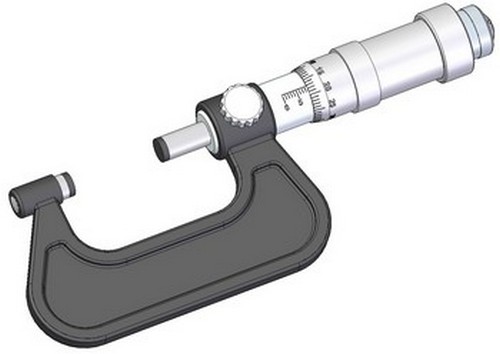
The micrometer consist of a semicircular frame having a cylidrical
extension, the barrel (sleeve), at its right end and a hardened anvil at the
other end. The bore of the barrel (sleeve) is threaded and a spindle screws
into the bore. The spindle carries a graduated thimble which turns at one with
it.
There are three types of micrometers which are commonly used: the outside
micrometer, the inside micrometer, and the depth micrometer.
OUTSIDE MICROMETERS
Outside micrometers are used to measure an outside distance or diameter to an
accuracy of .001 of an inch.
INSIDE MICROMETERS
Inside micrometers are used to measure an inside diameter to an accuracy of
.001 of an inch.
DEPTH MICROMETERS
Depth micrometers are used to measure depths to an accuracy of .001 inches.
Micrometers have been fitted with two refinements which are great help to the
user. The first of these is the spindle lock which is a device which enables
the spindle to be positively locked in any positions. The micrometer can be
set to a desired position and then locked. The second refinement is the
ratchet stop and this is a device placed on the end of the thimble. Only a
relatively slight pressure on the thimble can result in a considerable force
being exerted between the two anvils. If the force were to be excessive then
it would be possible to overstress the frame thus causing permanent damage to
the micrometer which would in turn lead to incorrect readings being obtained.
To overcome this problem the ratched stop is fitted and this drives the
thimble through a ratchet device.
READING A IMPERIAL MICROMETER
Reading a micrometer is only a matter of reading the micrometer scale or
counting the revolutions of the thimble and adding to this any fraction of a
revolution. The micrometer screw has 40 threads per inch. This means that one
complete and exact revolution of the micrometer screw moves the spindle away
from or toward the anvil exactly 1/40 or 0.025 inch.
The lines on the barrel conform to the pitch of the micrometer screw, each
line indicating 0.025 inch, and each fourth line being numbered 1, 2, 3, and
so forth. The beveled edge of the thimble is graduated into 25 parts, each
line indicating 0.001 inch, or 0.025 inch covered by one complete and exact
revolution of the thimble. Every fifth line on the thimble is numbered to read
a measurement in thousandths of an inch.
TO READ A MEASUREMENT AS SHOWN ABOVE.
Read highest figure visible on barrel.. . . . . 3 x 0,1in = 0.300 in.
Number of lines visible between the No. 3 and thimble edge. . . . . . . 1 x
0,025in = 0.025 in.
The line on the thimble that coincides with or has passed the revolution or
long line in the barrel . . .. . . . 16 x 0,001in = 0.016 in.
TOTAL = 0.300in + 0,025in +0,016in = 0,341in
READING A METRIC MICROMETER
The same principle is applied in reading the metric graduated micrometer, but
the following changes in graduations are used: The pitch of the micrometer
screw is 0.5 mm. One revolution of the spindle advances or withdraws the screw
a distance equal to 0.5 mm.
On the barrel the datum line is graduated with two sets of lines, the one
below the datum reading in millimetres and the set above reading in half
millimetres. The thimble scale is marked in fifty equal divisions, figured in
fives, so that each small division on the thimble represents 1/50 of 1/2mm
which equals 1/100mm , which is 0,01mm.

TO READ MEASUREMENT AS SHOWN ABOVE:
First note the whole number of mm divisions on the barrel (major divisions
below datum line) ........... 15 x 1,0mm = 15,00mm
Then observe whether there is a half mm visible (minor divisions above
datum line)
............3 x 0,50mm = 1,50mm
Finally read the line on the thimble coinciding with the datum line. This
gives hundredths of a mm. ........... 16 x 0,01mm = 0,16mm
TOTAL: 15,00mm = 1,50mm + 0,16mm = 16,66mm
DIGITAL MICROMETERS
Digital micrometer is very accurate and does involve the computations
needed by a standard micrometer. When the spindle and anvil come in contact
with the workpiece, the measurement can be read directly from a digital
display.
CARE OF MICROMETERS
1. Coat metal parts of all micrometers with a light coat of oil to prevent
rust.
2. Store micrometers in separate containers provided by manufacturer.
3. Keep graduations and markings on all micrometers clean and legible.
4. Do not drop any micrometer. Small nicks or scratchescan cause inaccurate
measurements.