V. Ryan © 2004 - 2009
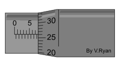
The micrometer is a precision measuring instrument, used by engineers. Each revolution of the rachet moves the spindle face 0.5mm towards the anvil face. The object to be measured is placed between the anvil face and the spindle face. The rachet is turned clockwise until the object is ‘trapped’ between these two surfaces and the rachet makes a ‘clicking’ noise. This means that the rachet cannot be tightened any more and the measurement can be read.
Using the first example seen below:
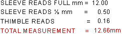
1. Read the scale on the sleeve. The example clearly shows12 mm divisions.
2. Still reading the scale on the sleeve, a further ½ mm (0.5) measurement can be seen on the bottom half of the scale. The measurement now reads 12.5mm.
3. Finally, the thimble scale shows 16 full divisions (these are hundredths of a mm).
The final measurement is 12.5mm + 0.16mm = 12.66
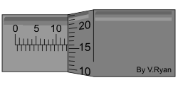
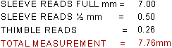
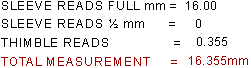
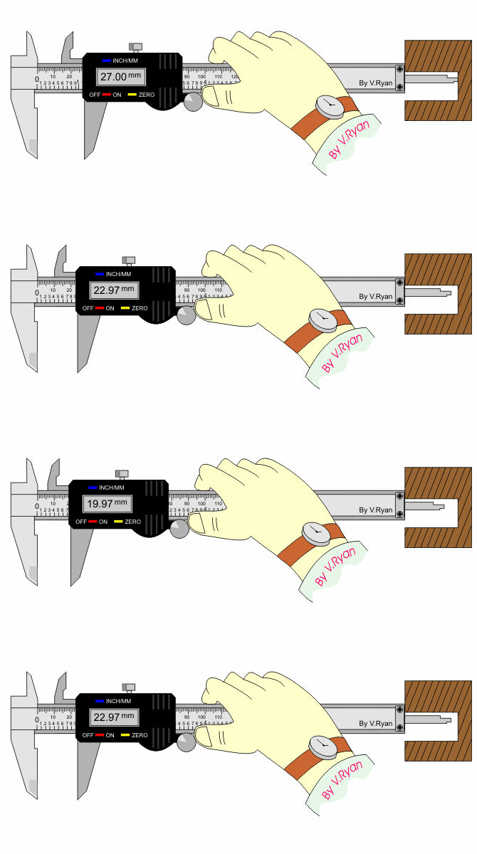
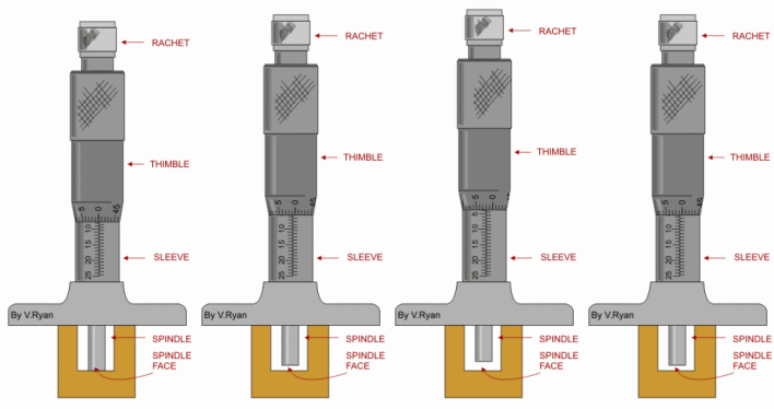
The depth gauge micrometer is a precision measuring instrument, used by engineers to measure depths. Each revolution of the rachet moves the spindle face 0.5mm towards the bottom of the blind hole. The diagram below shows how the depth gauge is used. The ratchet is turned clockwise until the spindle face touches the bottom of the blind hole. The scales are read in exactly the same way as the scales of a normal micrometer (see previous information sheets).
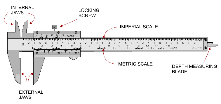
The Vernier Caliper is a precision instrument that can be used to measure internal and external distances extremely accurately. The example shown below is a manual caliper. Measurements are interpreted from the scale by the user. This is more difficult than using a digital vernier caliper which has an LCD digital display on which the reading appears. The manual version has both an imperial and metric scale.
Manually operated vernier calipers can still be bought and remain popular because they are much cheaper than the digital version. Also, the digital version requires a small battery whereas the manual version does not need any power source.
EXAMPLE 1: The external measurement
(diameter) of a round section piece of steel is measured using a vernier
caliper, metric scale.
MATHEMATICAL METHOD
A. The main metric scale is read first and this shows that there are 13 whole
divisions before the 0 on the hundredths scale. Therefore, the first number is
13.
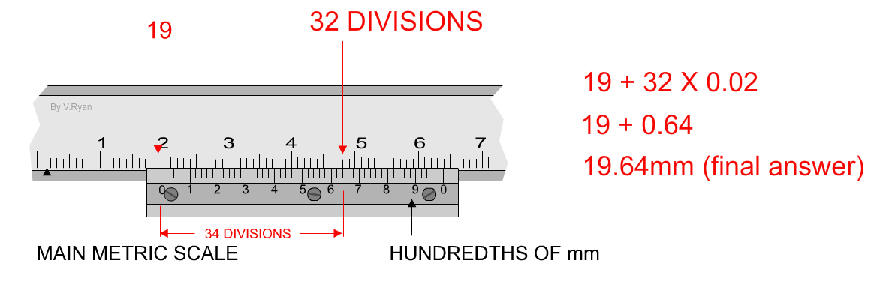
B. The’ hundredths of mm’ scale is then read. The best way to do this is to
count the number of divisions until you get to the division that lines up with
the main metric scale. This is 21 divisions on the hundredths scale.
C. This 21 is multiplied by 0.02 giving 0.42 as the answer (each division on the
hundredths scale is equivalent to 0.02mm).
D. The 13 and the 0.42 are added together to give the final measurement of
13.42mm (the diameter of the piece of round section steel)
COMMONSENSE METHOD
Alternatively, it is just as easy to read the 13 on the main scale and 42 on the
hundredths scale. The correct measurement being 13.42mm.

EXAMPLE 2: (To zoom in to see the scale - right click mouse and select zoom)
The Digital Caliper (sometimes incorrectly called the Digital Vernier Caliper) is a precision instrument that can be used to measure internal and external distances extremely accurately. The example shown below is a digital caliper as the distances/measurements, are read from a LCD display. The most important parts have been labelled.
Earlier versions of this type of measuring instrument had to be read by looking carefully at the imperial or metric scale and there was a need for very good eyesight in order to read the small sliding scale. Manually operated vernier calipers can still be bought and remain popular because they are much cheaper than the digital version. Also, the digital version requires a small battery whereas the manual version does not need any power source.
Digital calipers are easier to use as the measurement is clearly displayed and also, by pressing the inch/mm button the distance can be read as metric or imperial.
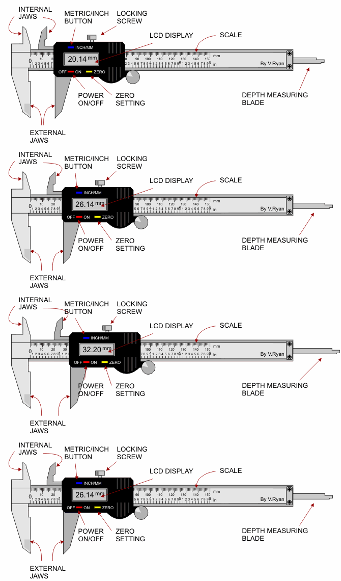
The display is turned on with the on/off button. The external jaws should then be brought together until they touch and the zero button should be pressed. The digital caliper can then be used to measure distances. Always go through this procedure when turning on the display for the first time.
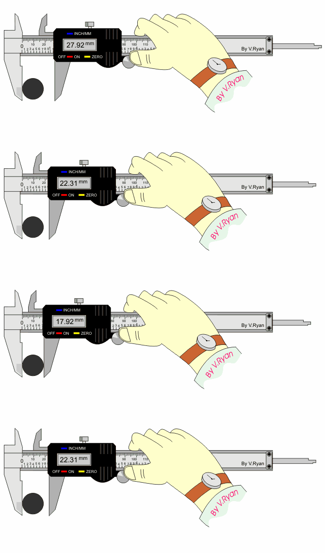
The material to be measured is placed between the external jaws and they are carefully brought together. The locking screw is tightened so that the jaws do not move apart. The digital display can then be read. The distance can be read by in metric and imperial by pressing the inch/mm button.
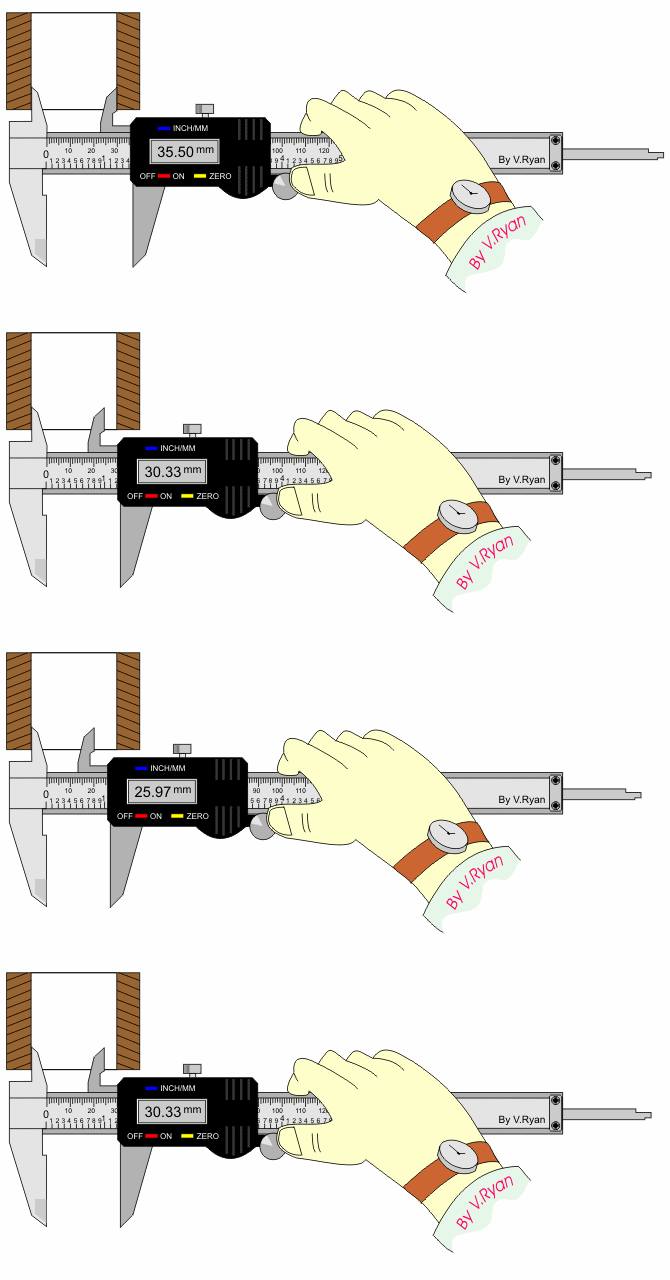
The example below shows a digital caliper being used to measure the internal diameter of a piece of copper tube. The internal jaws are adjusted carefully until they touch the internal ‘sides’. The locking screw is tightened so that an accurate measurement can be made even if the jaws are ‘knocked’ against the sides as the jaws are removed from the hole. The measurement is shown on the LCD display.
Measuring the depth of a hole can be very difficult. However, using a digital caliper makes this task easy. The base of the vernier caliper rests on the top of the hole and the depth measuring blade is adjusted until it touches the bottom of the hole. The locking screw is tightened and the measurement can be read on the LCD display.