Existen muchos libros y cursos sobre el trabajo en madera. Cualquiera de
ellos puede ilustrar la mayor parte de los trabajos comunes. Hay que tener en
cuenta que buena parte de la dificultad del trabajo de taller no consiste en
saber cómo hay que hacerlo sino en dominar la técnica y disponer de las
herramientas y tiempo necesario para lograrlo.
Uniones y ensambles
Las uniones de piezas de madera no sólo son necesarias para conseguir piezas
de mayor tamaño, sino que debido a que la madera sufre movimientos heterogéneos
debido a los cambios ambientales, una adecuada selección y combinación de los
cortes y dirección de las vetas, permite que el conjunto resulte más duradero.
Acoplamientos
Se denominan acoplamientos a las uniones realizadas por el canto para dar
como resultado una pieza de mayor anchura. Pueden hacerse con rebaje a media
madera, con rebaje machihembrado, mediante alma (las dos tablas con hendidura
hembra y un alma que hace de doble macho), con galletas internas (similar al
alma, pero no continua sino intermitente y normalmente ovalada o con llaves (como
galletas externas puestas en una sola cara normalmente con forma de doble cola
de milano).
Empalmes
Un empalme consiste en unir dos piezas por sus extremos dando como resultado
una pieza de mayor longitud. La resistencia del empalme depende en gran medida
de si la pieza va a estar en horizontal o vertical, de si la carga la va a
recibir de frente o de lado y de si ésta va a ser de compresión o de tracción.
Los empalmes pueden hacerse a media madera con testa recta o en sesgo con o
sin refuerzo de tornillos, con llave de cola de milano, con espigas redondas
internas, a horquilla (como un machihembrado grueso simple o doble), con dientes
triangulares (como un múltiple machihembrado triangular), etc.
Ensamble
La unión de dos piezas formando un ángulo puede realizarse por simple
superposición clavada o pegada o mediante un ensamble, que consiste en rebajar
una de las piezas en una zona llamada caja y en crear en la otra un saliente o
espiga que encaje perfectamente en la hendidura.
Si el ensamble se produce en los extremos de ambas piezas el resultado es un
ángulo. Pero si el extremo de una pieza se ensambla con la parte central de a
otra se crea un ensamble en T.
Los ensambles pueden ser a media madera a todo lo ancho, de palma o
entalladura (la caja no ocupa todo el ancho de la pieza y por tanto es menos
visible, a nedia madera en cola de milano, con caja de secciòn trapezoidal,
mediante clavijas, a inglete con o sin clavijas, en cola de milano por la testa,
etc.
Woodworking Joints
Woodworking joinery is the craft of connecting and securing the separate
members of the wooden construction to one another by means of specific cuts on
the ends and/or sides of the members. Woodworking joint is the spot where the
two pieces of wooden construction are joined together to form a rigid self
supporting and permanent construction. Woodworking joints can be formed between
the edges or between the end and the face, in the direction of the length, at
right angles or it may be at an angle, other than a right angle. Various glues
or fasteners (nails, screws, bolts…) are being used to increase the strength,
effectiveness and rigidity of woodworking joints. Since the main purpose of
woodworking joints is to join wooden parts together, their construction should
be done carefully, so it would not weaken the parts that are joining.
To be able to successfully design your wooden construction is necessary to bear
in mind two things: to know the right woodworking joint to use, and to know how
to make that woodworking joint in the right way.
In order to finish some woodworking project you will have to take a large number
of actions like project design, wood selection and preparation, finishing, but
durability and sturdiness of your wooden construction will mostly depend on the
choice and the manufacture of woodworking joints.
Every woodworking joint must fulfil important requirements:
- It must support the load transmitted from other parts of wooden
construction, or the load that has direct influence on the members of the
woodworking joint. This load includes the weight of the construction itself,
the external weight or the forces that influence your construction, various
internal and residual stresses.
- It must let the wood move as it expands and contracts with changes in
temperature and humidity
- It must provide suitable gluing surface or anchor for fasteners.
On some constructions the visual appearance is also important, so an
additional requirement for woodworking joints is to be either decorative or
unnoticeable. In both cases the woodworking joints must be properly and
accurately crafted.
Each of these joints has a name and is usually some variation of a hole or slot
on one timber, and a corresponding, matching projection on the other.
The purpose of our woodworking joints category is to introduce the basic types
and methods of making woodworking joints to the amateur carpenters, and for the
experienced carpenters to serve as a reminder, or to expand certain knowledge in
this field, if needed.
There are many types of woodworking joints; some can be made easily and the
others are quite difficult to make, but the practice will show you that the more
complex the woodworking joint is, the stronger it is.
The quality woodworking joints can be manufactured with the hand tools, but if
you need high productivity, you will have to rely on machines and power tools.
Woodworking joints can be divided into three categories, depending on the
functions they perform:
- Lengtening – To increase the effective length (Lap joint, end to
end butt joint, scarf joints, end to end half lap and sloping halving joint,
end to end finger joint and laminated joint)
- Widening – To increase the width (tongue and groove joints,
Butterfly key joint, edge to edge butt joints, dovetailed keys joint, edge to
edge butt joints reinforced with dowels, biscuits and splines)
- Framing - To terminate or to change direction (half lap joints,
mortise and tenon joints, rabbet joints, dado joints, bridle joints, miter
joints, dovetail joints, edge to face butt joints, end to edge butt joints,
end to face butt joints)
In cases when the wooden construction is not too loaded or when it has a
little weight itself, the dimensioning is not so much important. But if you
are dealing with big and expensive construction, damaging of which can cause
injuries or great financial loss, the dimensioning of woodworking and
carpentry joints is surely an important thing.
A bridle joint is similar to a mortise and tenon woodworking joint, thought
in most circumstances it would not be as strong. It is open ended mortise and
tenon joint. A bridle joint is quick and easy to make, since most of the waste
wood is removed with a saw.
| DIMENSIONING BRIDLE JOINTS |
 |
 |
| Bridle joint |
Double bridle joint |
| |
|
 |
|
| Triple bridle joint |
|
Angled bridle woodworking joint

Bridle woodworking joint at corner of
frame

Mitre bridle woodworking joint

Oblique angle bridle woodworking joint

Oblique bridle woodworking joint

Simple bridle woodworking joint

Stopped bridle woodworking joint

Table leg bridle woodworking joint to
rail

A butt joint is made by placing the end of one piece of wood against the side
of another and fastening them firmly to each other. A butt joint is not very
strong joint, but it can be reinforced in a number of ways.
| DIMENSIONING BUTT JOINTS |
 |
 |
| Edge to face butt joint reinforced with dowels |
End to edge butt joint reinforced with dowel |
| |
|
 |
|
| Edge to edge butt joint reinforced with spline |
|
Edge to edge butt woodworking joint

Edge to face butt woodworking joint

End to edge frame butt woodworking joint

End to face butt woodworking joint

Face to face butt woodworking joint

Types of reinforced butt joints
Edge to edge butt joint reinforced with
biscuits

Edge to face butt joint reinforced with biscuits

End to edge frame butt joint reinforced
with biscuits

End to face butt joint reinforced with
biscuits

Edge to edge butt joint reinforced with
dowels

Edge to face butt joint reinforced with dowels

End to edge butt joint reinforced with
dowels

End to end butt joint reinforced with
dowels

End to face butt joint reinforced with
dowels

Dowelling a moulded cap to the top of a
wooden bedstead post

Blind edge to face butt joint reinforced
with spline

Edge to Edge butt joint reinforced with spline

Edge to face butt joint reinforced with
spline

End to edge butt joint reinforced with
spline

End to face butt joint reinforced with
spline

Butt joints reinforced with fasteners
Edge to face pocket hole butt joint

End to face pocket hole butt joint

A strong way to join two or more pieces of board or plank to make a wider
piece is to cleat them.
A cleat is a piece of material fastened across the width of a board to prevent
its warping and to reinforce the butt joints between the boards. If the
surface is composed of several pieces, the cleat is also designed to hold them
together. It may be applied to the back of the pieces, or across the ends. As
the grain of the cleat is at right angles to that of the surface to which it
is fastened, and since wood shrinks and swells more across the grain than with
it, there is likely to be some movements of one on the other, and the
fastenings used to secure the cleat should be of such a nature as to allow it.
Otherwise, the edges of the board will be rigidly held, and shrinkage will
result in the formation of large cracks, by the splitting of the board
somewhere near the center. Screws are undoubtedly the best fastenings, as they
will yield, to some degree, without becoming loosened. nails frequently answer
every purpose; and dowels are sometimes used. Glue is unserviceable. When it
is used alone, the cleats soon drop off; and when used with other fastenings,
it either gives way entirely, or breaks at intervals, causing local cracks.

Side cleating is the more effective of the two methods, because the cleat may
be larger and, for this reason, the fastenings be applied to better advantage.
But, when exposed to view, side cleats are unsightly, and are often
objectionable because they increase the thickness of the piece as a whole. The
proportions of the cleat may vary with the duty expected of it.
Do not put the screws or nails in a straight line, but "stagger" them.

If the pieces are short they can be cleated across the ends. End cleating is
not so strong, but the cleats are out of the way and do not increase the
thickness of the piece. To supplement the fastenings, a narrow tongue may be
formed on the board to fit a corresponding groove in the cleat. Grooves can be
cut in both cleat and board, and a tongue or spline inserted. These operations
are done best bu machinery. End cleating does well on small work and where the
tendecy to warp is not too great. For heavier work, as doors, cleats on the
side are stronger, though not always desirable.
A dado joint is made by cutting a rectangular groove entirely across one
member into which the end of another member fits. Dadoes are cut across the
grain of the wood.
| DIMENSIONING DADO JOINTS |
 |
 |
| Tongue dado joint |
Through dado joint |
Through dado joint

Stopped dado joint

Blind dado joint

Tongue and dado joint

Dado and rabbet joint

Double dado joint

A Butterfly joint is a type of woodworking joint used either to hold two or
more pieces of wood together or to keep two halves of a board that have already
started to split from splitting further. A butterfly joint resembles two
dovetails connected at the narrow part.
Butterfly
key joint

Dovetail joints are so named from the shape of the piece which make the
joint. This is propably the strongest method for joining two pieces of wood. The
strength of the dovetail joint comes from the interlocking of the parts. There
is a great variety of forms of dovetail joints.
| DIMENSIONING DOVETAIL JOINTS |
 |
 |
| Through sliding dovetail joint |
Through dovetail joint |
| |
|
Anatomy of a through dovetail joint
 |
 |
| Dovetail joint angles |
Space between tails and pins |
Through dovetail joint for boxes

Through dovetail joint on carcase work

Blind dovetail joint

Lap dovetail joint for drawers

Blind secret mitre dovetail joint

Corner through dovetail joint

Dovetail spline joint

Dovetailed keys joint for wide surfaces

Through sliding dovetail joint

Half sliding dovetail joint

Stopped sliding dovetail joint

Wherever oblique cuts are to be made, great care is necessary in marking.
Place the pieces in the position shown in Fig. 1; the upper piece is to have
the tenon, or dovetail, the lower the mortise. With try-square and sharp
pencil, mark lines around three sides of each piece, at a distance from the
end equal to the width of the opposite piece, as shown at a, Fig. 1. These
pencil-marks should be very light, so as to be easily cleaned off with
sandpaper or smoothing plane.

Set the gauge at W, and mark the lines bb, Fig. 2. Set it at Q, and mark the
lines b’b’. Set it at X, and mark the line cc, and press the point only of the
gauge at d, d. Set the gauge at Y, and mark the line c'c', and the points e,
e. Bring the edge of the blade of the try square to coincide with the lines b
and c on the end of the mortise piece, and mark with the knife a line joining
them. Do the same for all the oblique lines, as shown in Fig. 1.
The tenon or dovetail (a, Fig. 2) is sawed out, and the sides of the mortise b
also cut with the saw. The mortise is finished with the chisel. A vertical cut
is made as at a, using the mallet, then one at b; these to be repeated until
one half through the piece, then cut on the opposite side. Avoid cutting into
the sides of the mortise by inclining the chisel. The same caution must be
observed in keeping some of the wood at c, until the last, when it is
carefully cut away, and the surface tested with the try square.

The sides of the mortise usually need a little paring before the tenon will
fit. This done, the pieces should go together easily, but without play or open
joints.
The joint ought to go together by light driving, and be perfectly square on
the indide between the working faces. If it is found to be satisfactory, take
it apart, apply a light coating of glue, and drive together again. When the
glue is hard, the joint may be sandpapered and squared.
Plain through dovetailed joint is rarely used upon anything but the most
expensive work, as it requires a high degree of skill to make economically. It
forms the strongest possible unreinforced joint for the corners of boxes,
chests, etc.
Laying out and cutting the dovetails
In making a dovetailed joint, some woodworkers layout and cut the pin, a,
first, which necessitates that the tails, b, should be marked and cut one at a
time. Good results may be obtained by this method, but it is slow, and is
rarely used upon practical work. The common method used by woodworkers is to
saw the dovetails, b, first, and mark the pins by the tails. If two or more
joints are to be dovetailed alike, the sides may be made into a bunch, and all
sawed at once.

1. Make the ends to be dovetailed perfectly square and true.
2. Gauge upon each side from these ends, the distance, C, or the thickness of
the piece to be dovetailed. It is very necessary to square the lines from the
face-edge, otherwise the joints are likely to be open on one side or the
other.
3. Place the dovetail piece, in the vise, end up, and face side toward the
workman, and on its squared end lay off lines as mn.
4. Having marked the lines mn, the slanting sides of the joints are marked
with the knife along the sliding T bevel set to a certain angle. If the angle
of the tail is too sharp, it is apt to be broken off when the pieces are
driven together.
5. Saw with a backsaw, in every case leaving the line of the piece which is
wanted.
6. Lay the pieces face down upon the bench, and with a chisel narrower than
the bottom of the cut, make one cut, as at a. This will minimize the tendency
of the chisel to push back, so that when the next cut is made upon the line d,
the wood will break into cut a, as at b, instead of pushing the chisel back of
line d, as at c, which will probably happen if cut a is omitted.
7. The gauge mark, d, at the bottom of the pin cut upon both sides should be
kept perfectly straight, and the cut be made exactly to this line, as a
straight piece of wood is to fit against it. The section of the cut should be
similar to d, and half of it cut from each side, holding the chisel as shown
by the try square at a, so as to cut under, which will allow the edges b, c to
fit closely against the pin. The novice is more than likely to make a cut that
will be full in the middle of the thickness of the board, shown by the dotted
line at d, which will prevent the pin from making a good joint at b and c.
8. Turn the piece over, face up, and make the cut from that side; clean out
the chips, or core.
Marking and cutting the pins
1. Place the dovetail piece, in the vise in a vertical position.
2. Place the pin piece upon the end of dovetail piece, as indicated. It is
important that the mark d (which is the same as d in previous steps), should
exactly coincide with the corner, or the back side, of pin piece.
Hold the upper piece in this adjusted position, while with a knife or pencil
you mark along the sides of the dovetails on the top of the pin piece. The
marks should appear like those of a. Mark the other ends in the same way. With
try-square and knife mark from the ends of the lines a, down to the
pencil-mark, as at b and c.
3. With backsaw, cut down to lines g, as shown by double lines, being careful
that in every case the cut is made outside of m and n, or that these lines are
left on the pin.
4. Turn the piece over in the vise so that the cuts p, g may be made in each
edge. These should be made exactly to the line upon each surface of the cut,
with a backsaw. This will cut out the corner, t. If the work has been
accurately done, these corners should not be touched again.

5. Clean out the spaces, r, with a chisel by the same method used in cutting
the tails.
6. If the work has been done with sufficient accuracy, there will be no need
of trimming either the pin or the tail to allow the two pieces to come
together and make a perfect joint. To attain this accuracy should be the
ambition of each beginners, as the skilful woodworker must be able to make
dovetails rapidly, surely, and without trimming. In cutting the pins, the
amateur is quite as likely to cut inside as outside of the lines, thus making
the pins too small; this tendency should be guarded against, and the pins, s,
left the exact size desired. In every case, the saw cut should be made with
such care that chiselling or fitting will be unnecessary, as it is quite as
likely to injure as to improve the dovetail joint.
7. The inside of both pieces should be smoothed and sandpapered before being
put together permanently; and care should be taken not to plane any off of the
back side of the pins, or they may be too small. If the pins fit too closely,
with a hammer bruise the corners of their ends a little, where they enter the
space between the tails; this makes them a little smaller, but when they are
glued together, the moisture of the glue will swell the pins to their normal
size. Glue the pieces together, being sure that the angle of the joint is
square; apply the glue sparingly. If the work has been done accurately, the
dovetail joint should be so tight that when it is set away for the glue to
harden, it will hold itself together without the aid of hand screws; though if
necessary, these may be used judiciously.
8. Smooth and sandpaper.
A finger joint or box joint is used to join two pieces of wood at a corner.
It is similar to a dovetail joint except that the pins are square and not
angled.
| DIMENSIONING BOX JOINTS |
 |
|
| Box joint |
|
| |
|
Box woodworking joint

Finger woodworking joint

Decorative finger woodworking joints

Miscellaneous finger woodworking joints

A half lap joint consist of two members notched to half thickness and lapped
on each other with the face flush.
| |
|
| DIMENSIONING LAP JOINTS |
 |
|
| Edge to Edge half lap joint |
Half lap joint terminology

Corner half lap joint

Oblique halving joint

Corner half lap joint with double
dovetail

Cross halving joint

Oblique cross halving joint

Cross halving joint with housed corners

T half lap joint

Tee halving joint

Blind half lap joint

Edge half lap joint

Full half lap joint

Dovetail half lap joint

Dovetail halving with shoulder

Stopped dovetail half lap joint

Half lap joint with one side dovetailed

Stopped half lap joint with one side
dovetailed

Mitered half lap joint

Carpentry tie half lap joint

Cross rail and upright halved joint

Halved joint on barrow wheels

Halved moulded joint

Interlocking cross half lap joint

Keyed dovetail half lap joint

Three member half lap joint

A miter joint is one formed by the meeting of two pieces at a corner, on a
line bisecting the right angle. The same class of joint maz be used on angles
greater or less than 90 degrees.
| DIMENSIONING MITER JOINTS |
 |
 |
| Mitre joint reinforced with spline |
Mitre joint reinforced with two spline |
| |
|
 |
 |
| Mitre joint reinforced with feather spline |
Mitre joint reinforced with two feather
splines |
| |
|
 |
|
| Mitre joint reinforced with dowels |
|
Edge miter joint

Edge miter joint reinforced with
biscuits

Edge miter joint reinforced with dowels

Edge miter joint reinforced with spline

End miter joint

End miter joint reinforced with
biscuits

End miter joint reinforced with dowels

End miter joint reinforced with spline

Frame miter joint

Frame miter joint reinforced with
biscuits

Frame miter joint reinforced with
dowels

Frame miter joint reinforced with
spline

Feather spline miter joint

The miter (mitre) joint is one formed by the meeting of two pieces at a
corner, on a line bisecting the right angle. A miter joint is a butt joint
which has been cut at an angle of 45 degrees. The same class of joint may be
used on angles grether or less than 90 degrees.
The miter (mitre) joint is extensively used in door and window making, cabinet
making, box making, joining of architraves, picture frames, and all sorts of
mouldings.
The only advantage of a mitred joint is that it shows only a line at the angle
and that the end wood is canceled. The miter joint is not a good joint for
wide pieces used flatways, for the wood will expand and contract more or less.
Shrinking in width will open a tapering crack from the inner corner; swelling,
from the outer corner.

There are some cases, as in making a picture frame of moulding, where mitring
is the only way in which the frame can well be put together, but as a rule,
particularly where strength is required, avoid the mitre.
A miter joint can be laid out and cut on rectangular stock without the use of
a miter box. However, stock with curved edges or surfaces requires the use of
the miter box. In any case, the miter joint can be made more quickly and more
accurately when a miter box is used.
Marking a miter joint
In making miter jointed frames, etc., take special care to have the face side
and face edge straight, square, and out of wind, and then be particular to
draw all lines and make all tests from the face side or face edge.
Marking a miter joint - Method 1
Mark with the try square and knife two lines across the middle of the strip
from A and E. Measure carefully the length AB, and lay it off on the face
edge, to obtain AC, then mark with the knife and blade of the try square, CB.
Do the same on the opposite side for the mark FD. From C and D mark lines on
the side square with the face edge.
Saw very accurately against the lines CB and DF

Marking a miter joint - Method 2
The easiest way for the woodworker to get the correct angle is to draw a
square at the end of the piece and then draw the diagonal.
The point A is as far from point C as the point B is from the point C, or the
distance AC is equal to the width of the piece.
Marking a miter joint with a sliding T bevel
When several miters are to be cut, sliding T bevel may be set to the 45
degrees and the other miter lines drawn with it.
Marking a miter joint - Method 4
To lay out a mitre, or the lines for the meeting of two pieces at any angle,
the pieces can be laid one above the other at a desired angle (for which
square or bevel can be used), and the points of crossing marked on each edge.
Lines connecting these points will give the angles for cutting.
Fastening a miter joint
Nails, or nails and glue are often used to fasten a mitered joint. If the
joint cannot be clamped securely for nailing, allow for slippage.
The vise can be used successfully for nailing a picture frame joint.
When nailing a miter joint from both sides, place the nails so they will not
strike each other and split the pieces.
The mitre joint is sometimes strengthened for box work and the like by fitting
a spline or tongue with the grain running across and not lengthways of the
joint. This, properly glued under pressure, makes a good joint and one much
superior to the plain miter joint.
Mitered dowel joint
Dowels with glue are also used for fastening a miter joint.
The miter joint is sometimes strengthened for box work and the like by fitting
a spline or tongue with the grain running across and not lengthways of the
joint. This, properly glued under pressure, makes a good joint and one much
superior to the plain mitre.

As in making the other woodworking joints, it is best to keep the stock in one
long piece until the construction work is finished.
Measure the exact width of the piece and lay off, near one end, a perfect
square, having as its sides two pencil lines and the two opposite edges of the
piece. ( It is not wise to measure from exact end of the stock, even though it
is square, as it makes the work of sawing more difficult.) Continue the two
pencil lines around the piece with the try square until they meet on the last
corner. Repeat this construction on the other end of the piece.
Using the edge of the try square as a straightedge, with a sharp knife draw
one diagonal in each of the squares thus constructed. Be very careful to make
the diagonals on the opposite sides agree with each other. The work will then
be ready for cutting out.

The work of sawing at an angle of 45 degrees is exactly the same as in
squaring an end, except that it is a little more difficult to hold the work
and start the saw correctly. When the sawing is finished, part of the knife
lines should remain. The ends should be smoothed to a perfect surface with the
block plane.
Next, measure the required length of each piece from the acute angle and
separate the pieces. To test the work, place the two halves of the joint
together in the inside angle of the try square. If they do not form a perfect
right angle, examine them carefully and find out what is wrong. If they
require trimming a little more with the block plane, work them separately.
Never try to plane them both at the same time. A sliding T bevel is a useful
tool for testing these aangles. It can be set to agree with the lines before
the joint is cut out and then used later on to test the finished work. The
work of constructing an angle of 45 degrees is explained fully here because a
woodworker must understand it. If he has a sliding T bevel, he can set it to
the angle thus constructed and use it in the same manner as the try square for
constructing the second half of the joint.
Fastening: The thin piece which is set into the corner is called a feather
spline. The joint is held together in the vise or with a clamp, and cut is
made across both parts of the miter joint at the same time at right angles to
the miter joint. The cut can be made with a coarse ripsaw, if one is on hand,
or by making two cuts with the backsaw. The spline is made by ripping a thin
piece from the edge of a block. For convenience in planing, the piece should
be considerably larger than the required finished dimensions. Next, both faces
of the joint are covered with a thin coating of glue. The inside of the cut
which is to receive the spline is also coated with glue. The joint is then put
together and clamped until the glue is dry. The clamps are then removed and
the surfaces cleaned by taking a light shaving from them with the plane.
Clamps should never be applied directly upon a finished surface. When the
miter joint is glued, a thin piece should be placed on each side of the work.
The clamp is then tightened and the joint driven together with light blows of
the mallet. The grain in the spline hould be at right angles to the miter.
After the glue is dry, the projecting ends of the spline are cut off flush
with the surface.
A mortise and tenon joint is the method of joining by forming a solid
rectangular projection in the one piece and cutting a corresponding cavity to
receive it in the adjoining piece. The cavity is called mortise and the solid
projection is called the tenon. There are a great manz modifications of this
joint.
Tenon and mortise terminology
 |
 |
| Tenon terminology |
Mortise terminology |
Through mortise and tenon joint

Corner through mortise and tenon joint

Blind mortise and tenon joint

Corner blind mortise and tenon joint

Angled haunched mortise and tenon joint

Angled haunched barefaced mortise and tenon joint

Application of haunched tenon joint to door frame


End wedged through tenon and mortise joint

Wedged through tenon and mortise joint

Barefaced blind tenon and mortise joint

Haunched tenon and mortise joint

Interlocking tenon and mortise joint for seat rails of chair to leg

Long and short shouldered tenon and mortise joint

Loose tenon and mortise joint

Open through tenon and mortise joint - Bridle joint

Round tenon and mortise joint

Tenon and mortise joint with mitered face

Tusk tenon and mortise joint

Twin tenon and mortise joint

Twin tenon and mortise joint for thick timber

Tenon and mortise joint reinforced with dowel

Tenon and mortise joint for fencing

Skewed tenon and mortise joint

Self wedging tenon and mortise joint

Drawboring - Pinning the tenon and mortise joint
Drawboring consists in boring a hole through the two sides of the mortise and
then boring a hole of the same diameter through the tenon, but slightly closer
to the shoulder of the tenon. When the joint is put together, the holes are
not in line and a pin driven through the hole will pull the joint together
very tightly. The amount of difference in the center line of the holes should
not be more than 1- 2mm (1/32in), and the pin should be pointed to prevent
splitting. This has to be done with judgment; for if the hole in the tenon is
too much out of line, driving the pin through puts too much strain on the end
of the tenon, on the pin, and on the sides of the mortise.
This kind of fastening is used chiefly on heavy framing where strength is the
most important thing to be considered.
To pin a mortise and tenon, mark a point with try square and gauge upon each
side of the mortise piece, fit the tenon in place, bore a hole, drive through
a snugly fitting pin, and trim off the projecting ends. In fine work bore from
both sides. The pin should be slightly pointed before driving.
If the pin is too far from the edge, its hold on the tenon will be weak and
the end of the latter may break out (shear), If too near the edge, the sides
of the mortise may tear or split off.

Pins are employed principally as a means of holding tenons in mortises. In
carpentry one pin, generally, is used in each joint, its diameter varying
from1/6 to 1/8 the width of the tenon. It is commonly placed at a distance
from the abutting cheeks of the mortise, equal to 1/3 the length of the tenon.
But to secure the maximum strength of the joint, its exact location in any
particular case must be fixed with reference to the character of the material,
and also to the relative thickness of the tenon and the cheeks of the mortise.
In joinery, it is found best to use two or more pins, and, whatever the
proportions of the joint may be, these rarely exceed 10mm in diameter. They
are inserted very near the abutting cheeks of the mortise, so that part of the
mortise between them and the shoulder of the tenon, will not shrink enough to
make an open joint. Square pins are better than round ones, but the latter are
more easily fitted and, therefore, more used.
Pinning the mortise joint
Bore with a bit through the face of the piece and mortise. The hole is not
bored all the way, but when the point shows through, turn the piece around and
bore from that side to complete the hole. By this means a clean cut is made on
both sides of the piece.


Place the tenon in the mortise and mark the center of the hole on it with the
point of the bit. Remove the tenon, and start the bit about 1mm nearer the
shoulder. The hole thus bores is not in a line with that of the mortise, but
when the pin is forced through, the pieces are brought closer together,
forming a stiffer and stronger joint.
The pin is planed to square, chamfered with plane or chisel to an octagon
shape, rounded and pointed with the chisel, which is just one half size. In
practice, the pin is driven in flush with the face of the mortise piece, the
protruding portion being either allowed to remain, or sawed off close.
For large through mortise joints, such as are seen in the heavy frames, two
pins are used.
The practice of drawboring is not to be commended, and, if indulged in at all,
great care and discretion must be exercised. In many cases, it puts a strain
on the joint which is nearly equal to its maximum resistance, and but little
strength is left to do work for which the joint is made. Frequently, the
mortise or tenon is split and rendered practically useless.
A good way to fasten tenons is to wedge them. This can be done whether the
tenon goes through the mortise piece or only part way, as in a blind mortise
and tenon joint.
The wedges can be driven between the tenon and the ends of the mortise, or, as
is often better, driven into cuts made in the tenon itself, thus spreading the
tenon towards the end, dovetail fashion, making it extremely difficult, or
impossible, to pull it out of the mortise.
To wedge a tenon, one or more saw cuts should be made in it and carried
farther than the wedges will extend. A small tenon can be split carefully with
a chisel. Before wedging, the ends of the mortise should be tapered toward the
side on which the tenon comes through. The mortise is tapered to match the
angle of each wedge. The tenon and mortise having been glued, and glue also
put into the saw cuts with a thin slip of wood, the tenon is fitted in place,
and the wedges, previously prepared and tapering quite gradually, are dipped
in the glue and driven down into saw cuts. Thus the end of the tenon is spread
into a dovetail until it fills the mortise tightly, making a very hard or
impossible to pull it out.
Wedged through tenon and mortise joint with a strain relief hole
Blind (Fox) wedged tenon and mortise woodworking joint
Blind wedging is sometimes resorted to when the mortise does not extend
through the piece. The wedges must not be so long as to break off or to
interfere with the tenon being driven home, and the bottom of the mortise
should be quite smooth where the wedges strike it, or the wedges may turn to
one side and not enter the tenon. The mortise is enlarged at the bottom. When
everything is ready, apply the glue, start the wedges in the cracks, and drive
the tenon to place. This will push in the wedges, spread the tenon at the end
and fix it firmly. If well done, it cannot be withdrawn.
Keyed mortise and tenon joint
For rough knockdown or outside furniture, the tenon can be cut longer than the
depth of the mortise, with a hole drilled into the protruding part of the
tenon and a key driven close to the outer face of the member which has the
mortise cut into it. When this is done, it is called a keyed mortise and tenon
joint.
Directions for key hole
Lay out the sides of the mortise for the key before the sides and shoulders of
the tenons are cut. From the shoulder line of the tenon, measure toward the
end a distance slightly less (about 1mm) than the thickness of the member thru
which the tenon is to pass. This is to insure the key's wedging against the
second member. Square this line across the face edge and on to the side
opposite the face side. On the top surface measure from the line just squared
around the piece a distance equal to the width the key is to have at this
point when in place (line A-B). Square a pencil line across the surface at
this point. In similar manner, measure and locate a line on the opposite side
(line C-D). Set the gage and mark the side of the mortise nearer the face edge
on the face side and side opposite. Reset, and from the face edge gage the
farther side of the mortise, marking both sides. This mortise may be bored ans
chiseled like the one preceding. As one side of the mortise is to be cut
sloping, a little more care will be needed.
A second method of laying out the mortise in the tenon consists in locating
the ends of the mortise by placing the key and scribing along the sloping
side. These lines are then squared across the two surfaces of the tenon. The
remainder of the procedure is similar to that just described.

Keys are made in quite a variety of shapes. Where two or more keys of the same
size are to be made, it is customary to plane all in one piece. Plane a face
side, a face edge, and shape the remaining edge as desired. The lines A-B and
CD, indicate the points at which measurements are to be made to determine the
length of mortise in the tenon which is to receive the key. These lines should
be laid off at a distance apart, equal to the thickness of the tenon.
To make the keys, get out one piece of the required size and long enough to
make all the keys wanted. Saw them to length, gauge the small ends, mark the
taper on the sides, and cut to the lines. They can also be got out in one
block, tapering, and then sawed into the required number of wedges; or a
rectangular block of the necessary size can be sawed slantingly.
A rabbet is a recess cut out of the end or edge of a board. When a piece is
butted into a rabbet, it is called a rabbet joint.
| DIMENSIONING RABBET JOINTS |
 |
|
| Rabbet joint reinforced with dowels |
|
| |
|
| |
|
Rabbet joint

Stopped rabbet joint

Mitered rabbet joint

Mitered lock rabbet joint

Dovetail rabbet joint

Edge to face rabbet joint

End to face rabbet joint

A scarf joint is formed where two pieces lap each other in the direction of
the grain, with flush surfaces. This joint is so constructed as to resist
tension and compression.
Scarfed joints are those in which the two timbers united are so cut and fitted
as to make the joint uniform in size with timbers. Some scarf joints by their
form are self sustaining, but, compared with the timbers they unite, are weak,
and are seldom used unless stengthened by bolts, or by bolts and fish pieces.
| DIMENSIONING SCARF JOINTS |
 |
 |
| Half lap scarf joint reinforced with dowels |
Tabled scarf joint |
| |
|
 |
 |
| Scarfed joint purlins reinforced with dowels |
Scarf joint reinforced with dowels |
Scarf joint

Half lap scarf joint

Dovetailed scarf joint

Tabled scarf joint

Bridle joint

Tenoned scarf joint

Double tenoned scarf joint

Edge halved scarf joint

Lapped scarf joint with bolts

Plated scarf joint

Scarf joint with Vee'd ends

Tabled scarf joint with straps

A tongue and groove joint provide a mechanical means of joining the edges of
narrow boards when forming a wider panel.
| DIMENSIONING TONGUE AND GROOVE
JOINTS |
 |
|
| Tongue and groove joint |
|
| |
|
Tongue and groove joint

Double tongued and grooved joint

Tongue and groove joint for nailing

Tongue and groove joint with bead

Tongued Grooved and Veed joint -
chamfer

Tongued Grooved and Veed joint - radius

Tongued Grooved and Veed joint - radius
with bottom

Dovetailed tongue and groove joint

Double dovetailed tongue and groove
joint

Dowels are round wooden pins of small diameter used to
strengthen (reinforce) a joint. They can be bought ready made and can be used
instead of nails or screws, or instead of mortising, dovetailing, etc. They
should be dipped in glue and driven at a tight fit into holes made for their
reception. Dowels may be made at the bench by the plane, or they may be
turned. When planed, they will be improved in section if driven through a
round hole in a piece of steel. They are supplied by the trade, of all
ordinary diameters and lengths.

While this joint is very simple in construction, it is not easy to make; and
before a beginner uses it on any practical work, he should try it on two
pieces of scrap lumber.
The utmost accuracy is necessary in marking the centers of the holes and
boring them, if satisfactory results are desired.
As compared with a mortised joint, when used upon common doors, the dowel is
not so satisfactory as the mortise, because the tenon reaches through the
stile, and the glue, collecting at the joint as the pieces are brought
together, makes a stronger connection there than at the end of the tenon at
the outside of the stile; therefore when the stile shrinks, it usually holds
at the joint, and its outside edge draws toward the joint, allowing the end of
the tenon to project beyond the stile the amount of the shrinkage. In a
doweled door, the joint would probably open. If a door which is exposed to the
weather is properly doweled, it will stand better than a mortised door in
which the tenon passes through the stile, since in the latter case, the
moisture will quickly find its way into the end of the tenon, and the door
will be rapidly destroyed. The mortises of an outside door should be of the
type known as "blind" or "fox wedging", as in this way the end of the tenon is
protected from the weather.
When used upon furniture and other work which is set up in a warm shop, and
when made of thoroughly kiln dried lumber, a properly made doweled joint is
perfectly satisfactory.

Uniting with dowels
Plane the surfaces of the blocks until perfectly flat, test them by bringing
the surfaces in contact, and note whether they touch all around. The dowel
joint is a weak one, and, unless the surfaces are flat and brought in close
contact, the dowels will be of no service in holding the pieces together.
A beginner often makes the mistake of leaving a slight error in fitting and
expects the clamps to squeeze the edges together. This can actually be done
with softwood; but such a correction is only temporary and the bad joint is
sure to open up later on, after the clamps have been removed.
Marking for dowels
Method 1.
The principal application of this method is in doweling the joints of a wide
board.
1. Place two pieces in the exact relative positions that they are to occupy
permanently.
2. Make a pencil mark across the joint upon the faces of both pieces at once,
as at AA.
3. With either a pencil or knife, square across both edges of the joint from
the marks, as at BB.
4. With a sharp gauge, make mark C, whic crosses BB. The intersection of these
two lines gives the center of the hole.
5. A scratch awl should be used to make a small hole at the above described
point, so that the bit will enter accurately, as otherwise it is apt to enter
a little to one side of the intersection, or to follow the grain.


Method 2.
This method of marking for dowels is sometimes used when it is not practicable
to use method 1, as in doweling irregular forms.
1. Drive small brads, straight into the end of piece A.
2. Cut off the heads of the brads at about 3 - 4mm from the wood.
3. Move piece B against A, being careful that the outsides are in just the
right relation to each other, and apply enough pressure to make the brads
leave imprints, in the end of piece B. These are the centers of the dowel
holes.
4. Pull the brads out of piece A; the holes thus made are the centers of the
dowel holes in that piece.

Method 3.
If it is desired to dowel irregular forms, or to make a number of joints just
alike, this method will not give good results and save a great deal of time,
but the pieces just alike will be interchangeable.
Make a templet of pasteboard; or, if it is to be used indefinitely, of steel,
and through it prick small holes in the position which will denote the exact
centers of the desired dowels, as at A. Place the templet upon the end of
piece B, with the corner C of the templet at C of piece B, and flush with the
face side; with a pricker, mark through the holes of the templet the centers
of the dowels 1,2. Place D of the templet on the edge of piece F, and flush
with the face side, so as to coincide exactly with D of piece F. Through the
holes A of the templet, mark 1,2 upon the edge of piece F. This method is much
used upon large or irregularly shaped work of all kinds, as it permits of
accurate work, and needs no tools but the templet and the pricker.

Method 4.
Place the boards to be doweled side by side in the vise, the face sides out,
and even the joined edges. Square lines across the two edges with knife and
try square at points where it is desired to locate dowels. Set the gage for
about half the thickness of the finished board and gauge from the face side
across knife lines. At the resulting crosses bore holes of the same diameter
as that of the dowel.
Method 5
Still another method consists in turning on the late dowel markers (dowel
centers). By having a variety of sizes with the centers accurately placed,
time may be saved over the methods just described. To use this marker, bore
the holes in one of the members, insert markers of the proper sizes and then
press this member against the second member.

The dowel pins are prepared next.
This can be done best on a turning lathe; but if the shop has no lathe, they
can be made by hand. A square stick is first prepared. This is rounded with
the block plane, turning the stick with the left hand and planing with the
right hand until one half of its length is rounded. The piece is then reversed
and the other hanf is rounded. In connection with this work it is best to try
the dowel pin first by boring a hole of the required size in a piece of scrap
lumber. The rounded stick should fit tightly by light driving. When finished,
the stick is cut into the proper lengths and the ends are slightly chamfered
so that they will enter the holes without wedging.
An appliance called a dowel plate is often used for making dowel pins, and is
very useful. It consists of a steel plate with holes of various sizes bored
through it. The edges of the holes are countersunk so that they have a sharp
edge on one side of the plate. The dowel stick is partly rounded and then
driven through the hole in the plate. The edges of the steel plate scrape off
the remainder of the waste material and make the dowel stick round.

Gluing the dowels
Before gluing, the work should be fitted together, as it is very awkward to
make changes after beginning to glue. If the parts fit accurately take the
joint apart, glue around the inside of one of the holes with a small stick,
dip one end of a dowel in the glue and drive into place. Wipe off any
superfluous glue and repeat the process with each of the dowels in that half
of the joint. Leave to dry. Then see that there is no hardened glue on the
dowels or on the faces of the joint, and glue them as before into the other
piece, this time putting glue on the flat surfaces which are to come together.
Clamp the whole firmly and leave to dry.
It should be clamped at points about 150mm apart. The clamps should pull
evenly and not bend the boards side ways. This can be prevented by putting the
clamps on alternately first from one side and then from the other.
It is not wise to use a dowel longer than is necessary; one extending from
20mm to 30mm each side of the joint will holds as well as one reaching farther
into the edge of the side wood, for the reason that the wood between the joint
and the end of the dowel will shrink, and the longer the dowel, the greather
the width of wood there is to be affected. A longer dowel may sometimes be
necessary in the wide stile of a door, to give sufficient strength to resist
the slamming which a door receives. A dowel should be 1 - 3mm shorter than the
aggregate depth of the holes which are to receive it, and should be made loose
enough to be pushed in with fingers, but not loose enough to fall out or to be
rattled around. The ends of the dowel should be chamfered. This allows some of
the glue to be forced up between the dowel and the side of the hole, and not
all pushed before the end of the dowel, which would be the result if the dowel
were square ended; unless the dowel were too loose, in which case it would not
have its full strength, as the joint would not be wood to wood.
In boring holes for dowels, it is custom of many workmen to use one of the
many forms of bit stops upon the market,in order to insure a uniform depth to
all of the holes. This uniformity is necessary, otherwise the dowels will have
to be cut to different lengths, which will require care and time to locate in
their proper holes while the joint is being glued up, just when every second
of time is precious.
Dowels are usually made of hard, strong woods, such as maple or birch. They
can be obtained from hardware supply companies at a reasonable price.
Dowelling mistakes
A - Dowels not properly centered
B – Dowel hole not perpendicular

My way of making a neck pocket
The correct neck alignment on any guitar is extremely important: the outer
strings have to run parallel to the fingerboard edges from the nut to the bridge
and the neck center line should line up correctly with the body center line. If
the neck is not mounted dead straight, parts of an outer string might end up off
the fingerboard. The pocket that will accept the neck is best cut with a
flush-trimming cutter bit with shank-mounted ball bearing. For this purpose you
need an accurate 1:1 template of the neck shape. Such templates are commercially
available for standard Fender-style necks but I find it difficult to fasten them
correctly aligned.
Personally I prefer using a jig made up of two long, 19mm (3/4")-thick and
about 50mm (2")-wide boards plus another short piece of wood to using just one
template for defining the shape of the neck pocket. The straight edges required
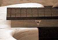
on the boards are easy to plane. As you will see in picture 1 the neck profile
hasn't been shaped but the fingerboard is glued on and the neck blank is already
trimmed flush to the fingerboard on the table router using a flush-trimming bit
with shank-mounted ball bearing.
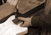
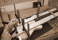
Place the neck in exactly the position it will eventually be in and fasten it on
the body provisionally using a clamp and a clamping caul.
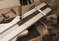
Then put the two straight, narrow boards to the left and right of the neck and
clamp them to the neck at the 1st and 14th fret (the second clamp is missing in
the picture above).
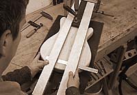
A rule taped down across the body in the bridge area - a zero-mark in the middle
of the rule would come in very handy - helps to center the neck. If the guitar
is to have a pickguard, fasten it temporarily for aligning the neck. The neck
can now be aligned very accurately by lining it up on center with the body.
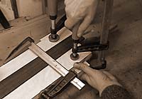
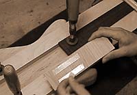
When the correct neck alignment has been found fix the position of the two
boards by fastening each of them with two clamps at the lower body end. It is
important that the four clamps are placed out of the way of the router. At the
upper end of the neck the distance between the two boards is fixed by placing a
short scrap board under the neck and across it. Fasten the board with two
clamps.
Now insert a third piece of wood at the lower end of the neck. It doesn't matter
if this piece doesn't fit in tight because the ball bearing of the cutter bit is
large enough to not follow into any gaps in the corners. If the end of the neck
is rounded off, the front end of the piece of wood has to be cut and filed
accordingly to ensure it fits in. Since the piece of wood and the two boards are
all 19mm (3/4") thick, it would also fit under a fingerboard that is longer than
the neck. Fix the piece of wood with thin double-stick tape. Thick tape such as
that used for fastening mirrors would be far too strong for this purpose and
would make it very difficult to remove the piece of wood afterwards. Apart from
that the marks left by such tape would also be very difficult to get rid of.
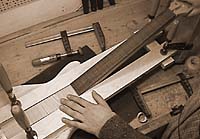
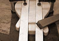
The two clamps placed on the boards right at the beginning can now be removed in
order to allow removing the neck. And here it is an exact aligned 1:1 template
for your ball-bearing cutter bit.
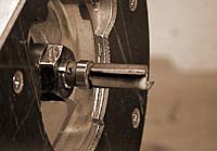
How thick the template has to be made depends on the length of your cutter bit -
the ball bearing must obviously touch the edge of the template. Flush-trimming
cutter bits with shank-mounted ball bearing are commonly 1" long. There are also
3/4"- and 1/2"-long bits, but these are less common and more difficult to get
hold of. I use a 1"-long cutter bit, which is why the template has to be quite
thick.
The depth of the neck pocket depends on the bridge used: when the saddles on the
bridge are set to their lowest position the strings should touch the
fingerboard. The pocket depth is therefore "thickness of neck plus fingerboard
(25mm or 1") minus lowest possible saddle height".
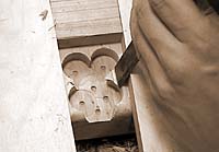
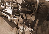
Pre-drill the pocket to keep stress on the router bit to a minimum and clean it
up with a chisel. If you use a brad point bit or a Forstner bit, always take its
point into account. Lower the drill bit onto the wood until its point almost
touches the surface. Now set the drilling depth just a little shallower, to be
on the safe side. The depressions left by the point of the bit are finally
routed off when you cut the pocket out in several passes.
A mistake commonly made when adjusting the router is to not take the thickness
of the template into account. Put the the router on the template and lower the
bit until it touches the body surface and then lock it. The cutting depth can
now be set by putting a shim of appropriate thickness under the depth stop.
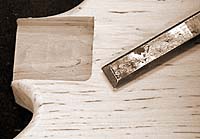
You can round off the neck end according to the radius of the router bit or you
square up the corners of the neck pocket with a chisel. The tighter the neck
fits into the body and the flatter the contact surfaces are, the better the
sound transmission will be. But don't overdo it - if the neck fits in too tight
it won't go in after finishing the neck.
--
This way of making neck pockets (and much more) can be found in my books "Building Electric
Guitars" and "E-Gitarrenbau"


